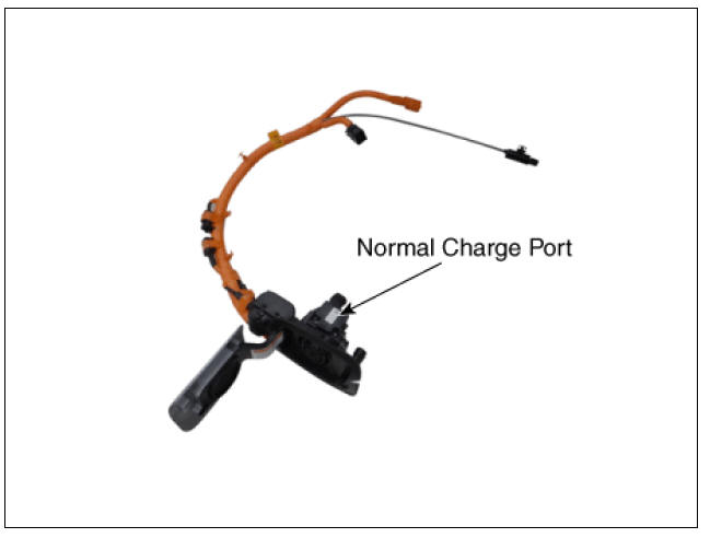
KIA Niro: Сharge port
Description
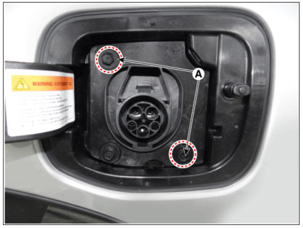
Location of normal charge port in the front fender of vehicle. The charge starts when the ICCB or the is connected to charge port.

Removal
Warning
- Be sure to read and follow the "General Safety Information and Caution" before doing any work related with the high voltage system. Failure to follow the safety instructions may result in serious electrical injuries.
- Be sure to read and follow the "High Voltage Shut-off Procedures" before doing any work related with the high voltage system. Failure to follow the safety instructions may result in serious electrical injuries.
- Turn ignition switch OFF and disconnect the negative (-) battery cable.
- Shut off the high voltage circuit.
(Refer to Hybrid Control System - "High Voltage Shutoff Procedure")
- Remove the head lamp (LH).
(Refer to Body Electrical System - "Head Lamp")
- Remove the LH front wheel & tire and wheel house cover.
- Disconnect the normal charge port connector (A).
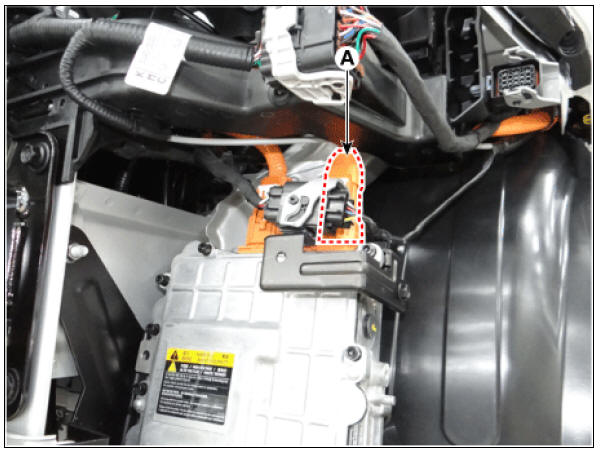
- Remove the normal charge port mounting bolts (A).
Normal charge port mounting bolt : 9.8 - 11.8 N*m (1.0 - 1.2 kgf*m, 7.2 - 8.7 lb*ft)
- Remove the normal charge port from the vehicle.

Installation
Warning
- Be sure to read and follow the "General Safety Information and Caution" before doing any work related with the high voltage system. Failure to follow the safety instructions may result in serious electrical injuries.
- Be sure to read and follow the "High Voltage Shut-off Procedures" before doing any work related with the high voltage system. Failure to follow the safety instructions may result in serious electrical injuries.
- Install the chager port in the reverse order of removal.
Specification

Description
The Low Voltage DC/DC is integrated into the HPCU. It charges the auxiliary
battery as a substitute
for generator by converting the high voltage (DC 270V) from the high voltage
battery into low voltage
(DC 12V).
READ NEXT:
 Low Voltage DC/DC Converter (LDC)
Component Location
Low Voltage DC/DC Converter (LDC) (HPCU)
Low Voltage DC/DC Converter (LDC) power output
terminal (+) (DC 12V)
Low Voltage DC/DC Converter (LDC) ground terminal (-)
Schematic Diagram
Low Voltage DC/DC Converter
Hybrid Drive Motor Assembly Repair procedures
Description
The hybrid motor system is equipped with two electric motors - HSG and
drive motor.
The traction motor operates to move the vehicle, to reduce Noise,
Vibration, and Harshness (NVH) while driving and to
improve fuel efficienc
SEE MORE:
Cruise Control (CC)
Cruise indicator
Set speed
Cruise Control will allow you to drive at
speeds above 30 km/h (20 mph) without
depressing the accelerator pedal.
Cruise Control operation
Setting speed
Accelerate to the desired speed,
which must be m
Release Residual Pressure in Fuel Line | Fuel Tank Repair procedures
Warning
Whenever the high pressure fuel fuse, fuel pipe, delivery pipe, or injector is removed immediately after shutting off the engine, an injury may be caused by the release of highly pressurized fuel.
Release the residual pressure in the
Categories
- Home
- KIA Niro EV, Hybrid - Second generation - (SG2) (2021-2024) - Owner's manual
- Kia Niro - First generation - (DE) (2017-2022) - Service and Repair Manual
- Contact Us