KIA Niro: Release Residual Pressure in Fuel Line | Fuel Tank Repair procedures
Kia Niro - First generation - (DE) (2017-2022) - Service and Repair Manual / Engine Control / Fuel System / Fuel Delivery System / Release Residual Pressure in Fuel Line | Fuel Tank Repair procedures
Warning
Whenever the high pressure fuel fuse, fuel pipe, delivery pipe, or injector is removed immediately after shutting off the engine, an injury may be caused by the release of highly pressurized fuel.
Release the residual pressure in the high pressure fuel line by referring to the "Residual fuel
pressure release procedure" below before removing any high pressure fuel system components.
Warning
Wear safety glasses and fuel resistant gloves.
- Switch "OFF" the ignition and disconnect the negative (-) battery terminal.
- Remove the fuel pump fuse (A).
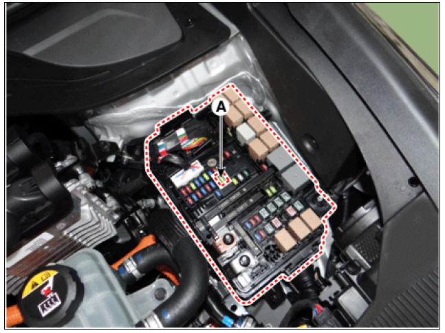
- Reconnect the negative (-) battery terminal.
- Run the engine for about one minute to lower the pressure in the low pressure line.
- Switch "OFF" the engine.
- Disconnect the low pressure fuel line quick connector at the High Pressure Pump. Use rags to cover opening and catch spills while removing the fuel line.
- Start the engine and let it idle until the engine stops. At this point the pressure should be under 30 psi.
- Proceed with the service or repair. Use rags to cover opening and catch spills when opening up the high pressure system.
- Reinstall / re-connect all components in reverse order of removal. Start engine and confirm proper operation, and make sure there are no fuel leaks.
- After completing, clear DTC(s) using KDS scan tool (the procedure described above will cause DTC to set).
Fuel Tank Repair procedures
Removal
- Release the residual pressure in fuel line.
(Refer to the Fuel Delivery System - "Release Residual Pressure in Fuel Line")
- Switch "OFF" the ignition and disconnect the negative (-) battery terminal.
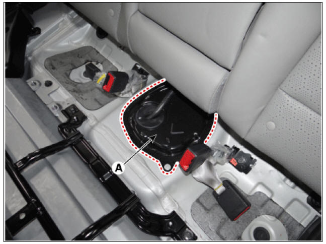
- Remove the rear seat cushion.
(Refer to Body - "Rear Seat Assembly")
- Fuel pump service cover (A).
Warning
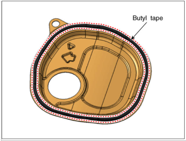
- When reinstalling a protective cover for a fuel pump, remove the existing butyl tape and apply a new one.
- Before assembling the protective cover, ensure that the temperature of the butyl is about 30º C using a hair dryer or a heat gun.
Warning
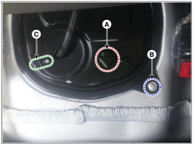
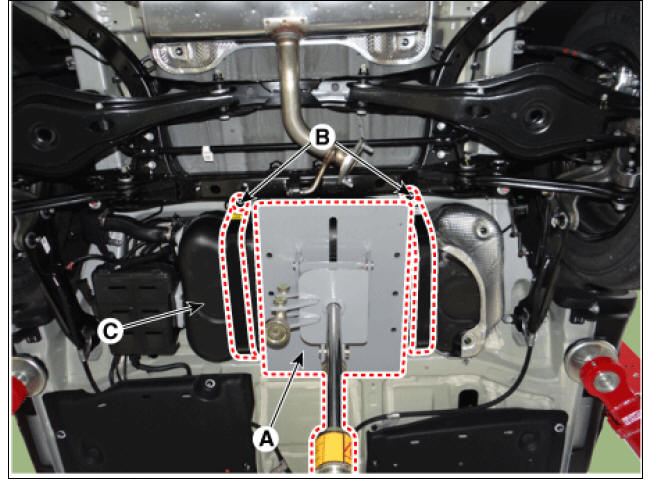
When installing the protective cover for the fuel pump, pay attention to the installation direction of the grommet and the protective cover.
- The arrow (A) should be in the forward direction of the car.
- Align the bulging part of the vehicle body (B) with the hole of the protective cover.
- Align the bulging part of the grommet (C) with the bulging part of the protective cover.
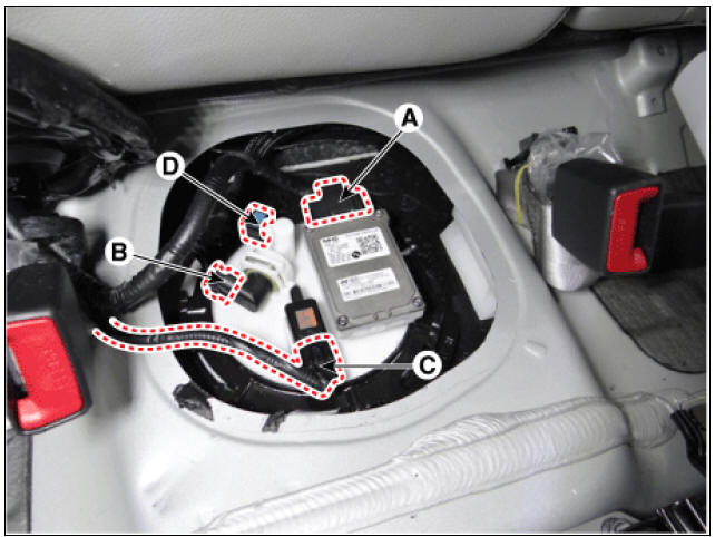
- Remove the fuel pump control module connector (A).
- Disconnect the fuel pressure sensor connector (B).
- Disconnect the fuel tank pressure sensor (C).
- Disconnect the fuel feed tube quick-connector (D).
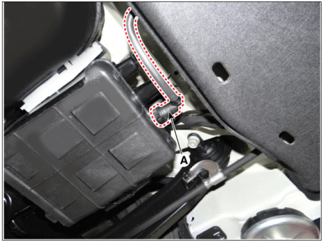
- Lift the vehicle.
- Disconnect the vapor tube quick-connector (A).
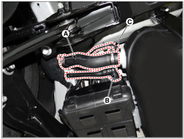
- Disconnect the fuel filler hose (A) and ventilation tube hose (B).
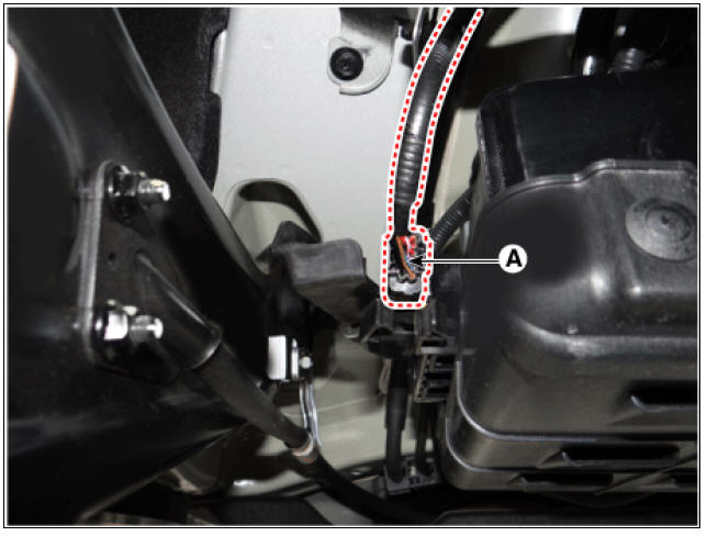
- Disconnect the vapor tube quick-connector (A).
- Disconnect the fuel tank isolation valve extension connector (A).
- Support th tank on a jack (A).
- Remove the fuel tank band mounting nuts (B).
- Remove the fuel tank (C) from the vehicle.

Installation
- Install in the reverse order of removal.
READ NEXT:
 Fuel Pump Repair procedures
Fuel sender
Turn the ignition switch OFF, and then remove battery (-) terminal.
Remove the fuel pump assembly.
Using an ohmmeter, measure the resistance between terminals 1 and 6 of
sender connector (A) at
each float level.
Fuel Filter Repair procedures
Removal
Remove the fuel pump.
(Refer to Fuel Delivery System - "Fuel Pump")
Disconnect the fuel pump motor connector (A) and fuel sender connector
(B).
Lift the fixing hook (A) by using a common driver, and then remov
SEE MORE:
How to disconnect charging connector in emergency
Before disconnecting the charging
connector, make sure the doors are
unlocked. When the door is locked,
the charging connector lock system
will not allow disconnection. To prevent
charging cable theft, the
charging connector cannot be
Regenerative braking mode
Operation
Pull the left side (-) of the paddle
shifter to increase regenerative braking
and deceleration.
Pull and hold the left side (-) of the
paddle shifter to reach MAX and stop
the vehicle.
Pull the right side (+) of the
Categories
- Home
- KIA Niro EV, Hybrid - Second generation - (SG2) (2021-2024) - Owner's manual
- Kia Niro - First generation - (DE) (2017-2022) - Service and Repair Manual
- Contact Us