KIA Niro: Pre-Charge Relay
Specification

Description
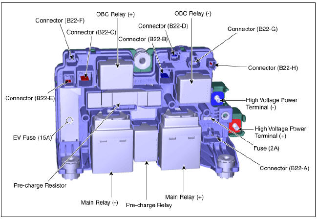
The Power Relay Assembly (PRA) consists of the positive and negative main relays, pre-charge relay, pre-charge resistor and battery current sensor. It is located inside the battery pack assembly and controls the high voltage power circuit between the high voltage battery and inverter by the control signal of BMS ECU.

PRA Operation Sequence

Circuit Diagram

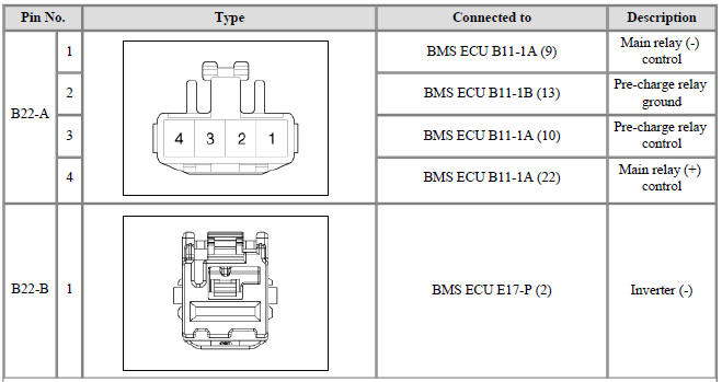
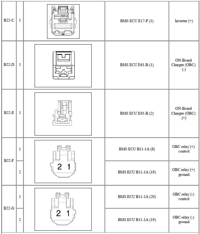
Harness Connector and Terminal Function

Pre-Charge Relay Repair procedures
Warning
- Be sure to read and follow the "General Safety Information and Caution" before doing any work related with the high voltage system. Failure to follow the safety instructions may result in serious electrical injuries.
- Be sure to read and follow the "High Voltage Shut-off Procedures" before doing any work related with the high voltage system. Failure to follow the safety instructions may result in serious electrical injuries.
- Turn ignition switch OFF and disconnect the negative (-) battery cable.
- Shut off the high voltage circuit.
(Refer to Hybrid Control System - "High Voltage Shut-off Procedures")
- Remove the power relay assembly.
(Refer to High Voltage Battery System - "Power Relay Assembly")
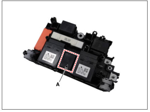
- Remove the pre-charge relay (A).

Installation
Warning
- Be sure to read and follow the "General Safety Information and Caution" before doing any work related with the high voltage system. Failure to follow the safety instructions may result in serious electrical injuries.
- Be sure to read and follow the "High Voltage Shut-off Procedures" before doing any work related with the high voltage system. Failure to follow the safety instructions may result in serious electrical injuries.
- Install the pre-charge relay in the reverse order of removal.
Inspection
Warning
- Be sure to read and follow the "General Safety Information and Caution" before doing any work related with the high voltage system. Failure to follow the safety instructions may result in serious electrical injuries.
- Be sure to read and follow the "High Voltage Shut-off Procedures" before doing any work related with the high voltage system. Failure to follow the safety instructions may result in serious electrical injuries.
High voltage pre charge relay switch resistance
Use multi tester (relay OFF)
- Shut off the high voltage.
(Refer to "High Voltage Shut-off Procedures")
- Remove the high voltage battery rear cover.
(Refer to "High Voltage Battery System - "Case")
- Remove the inlet cooling duct.
(Refer to Hybrid Control System - "Cooling Duct")
- Measure the resistance between the high voltage power terminal (+) and the inverter power terminal (+).
Specification : ¥Ω (20ºC (68ºF))

KDS - relay ON
- Connect the KDS to the Data Link Connector (DLC).
- Turn the ignition switch ON.
- Activate the pre-charge relay by using "Actuation Test" on the KDS as shown in the illustration below.
Warning
When the relay is ON, there is a relay operation sound.
High Voltage Per-Charge Relay Coil Resistance
- Shut off the high voltage.
(Refer to "High Voltage Shut-off Procedures")
- Remove the power relay assembly.
(High Battery System - "Power Relay Assembly")
- Check for continuity between the terminals using an ohmmeter.
Specification : 50 ~110 Ω (20ºC(68ºF))

READ NEXT:
 Pre-Charge Resistor
Specification
Description
Pre-Charge Resistor is integrated into the Power Relay Assembly (PRA). It
protects the high voltage circuit by limiting the
current while the inverter capacitor is being charged.
PRA Operation Sequence
Cir
Battery Current Sensor
Specification
Battery Current Sensor
Specification
Description
Battery Current Sensor is integrated into the Power Relay Assembly (PRA) and
measures the current
of the high voltage battery during charging or discharging.
Installation
Battery Temperature Sensor
Specification
Air Inlet Temperature Sensor
Battery Temperature Sensor (Side of cell)
Description
Battery Temperature Sensor is installed inside the high voltage battery pack
assembly. It measures the temperature of t
SEE MORE:
Cylinder Head Cover Components and components location | Cylinder Head Cover Repair procedures
Components
Camshaft bearing cap
Camshaft front bearing cap
Exhaust camshaft
Intake camshaft
Exhaust CVVT assembly
Intake CVVT assembly
Cylinder head
Cylinder head gasket
Retainer lock
Retainer
Indicators And Gauges - Troubleshooting
Troubleshooting
Error Item:
Screen display
Failure
symptom:
LCD screen
does not turn
on
Inspection items:
Connector
attachments
Components
Detailed inspections:
Check the
connector
attachments
Check B+, IGN and
Categories
- Home
- KIA Niro EV, Hybrid - Second generation - (SG2) (2021-2024) - Owner's manual
- Kia Niro - First generation - (DE) (2017-2022) - Service and Repair Manual
- Contact Us