KIA Niro: Battery Temperature Sensor
Specification
Air Inlet Temperature Sensor

Battery Temperature Sensor (Side of cell)


Description
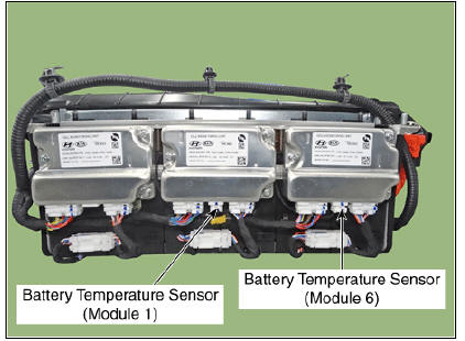
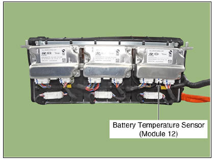
Battery Temperature Sensor is installed inside the high voltage battery pack assembly. It measures the temperature of the battery module 13, 20, 24 and air inlet sub high voltage battery module 1, 6, 12. In addition, it integrates the voltage sensing wiring for each module.
Main High Voltage Battery Temperature Sensor

Sub High Voltage Battery Temperature Sensor

Circuit Diagram


Main High Voltage Battery Temperature Sensor
Removal
Warning
- Be sure to read and follow the "General Safety Information and Caution" before doing any work related with the high voltage system. Failure to follow the safety instructions may result in serious electrical injuries.
- Be sure to read and follow the "High Voltage Shut-off Procedures" before doing any work related with the high voltage system. Failure to follow the safety instructions may result in serious electrical injuries.
Main High Voltage Battery Temperature Sensor
- Switch "OFF" the ignition and disconnect the negative (-) terminal of the auxiliary 12V battery.
- Shut off the high voltage circuit.
(Refer to Hybrid Control System - "High Voltage Shutoff Procedure")
- Remove the main high voltage battery system assembly.
(Refer to High Voltage Battery System - "Removal")
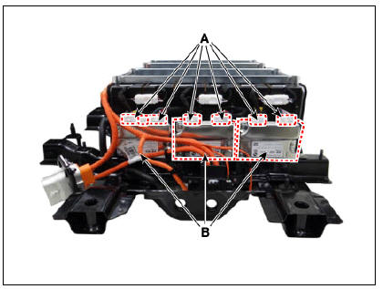
- Disconnect the cell monitoring unit connector (A).
- Remove the cell monitoring unit (B) after loosening the mounting nut and screw.
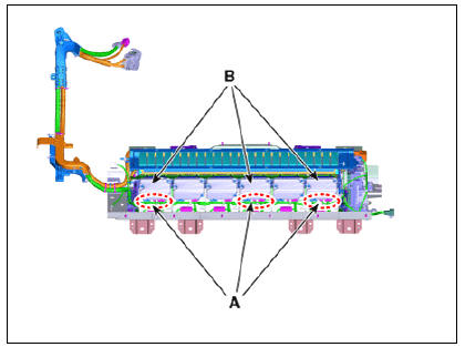
- Remove the battery temperature sensor (A).

Sub High Voltage Battery Temperature Sensor
- Switch "OFF" the ignition and disconnect the negative (-) terminal of the auxiliary 12V battery.
- Shut off the high voltage circuit.
(Refer to Hybrid Control System - "High Voltage Shutoff Procedure")
- Remove the sub high voltage battery system assembly.
(Refer to High Voltage Battery System - "Removal")
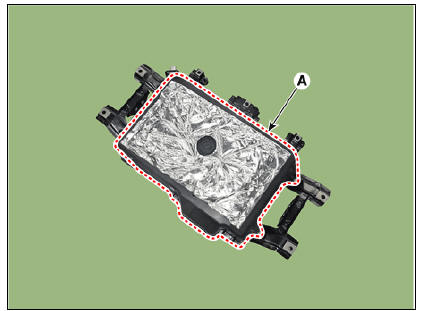
- Remove the high voltage battery watertight case (A).
- Disconnect the cell monitoring unit connector (A).
- Remove the cell monitoring unit (B) after loosening the mounting screw.
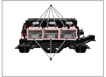
- Remove the battery temperature sensor (A).

Installation
Warning
- Be sure to read and follow the "General Safety Information and Caution" before doing any work related with the high voltage system. Failure to follow the safety instructions may result in serious electrical injuries.
- Be sure to read and follow the "High Voltage Shut-off Procedures" before doing any work related with the high voltage system. Failure to follow the safety instructions may result in serious electrical injuries.
- Install the battery temperature sensors in the reverse order of removal.
Inspection
Warning
- Be sure to read and follow the "General Safety Information and Caution" before doing any work related with the high voltage system. Failure to follow the safety instructions may result in serious electrical injuries.
- Be sure to read and follow the "High Voltage Shut-off Procedures" before doing any work related with the high voltage system. Failure to follow the safety instructions may result in serious electrical injuries.
- Shut off the high voltage circuit.
(Refer to "High Voltage Shutoff Procedure")
- Connect the KDS to the Data Link Connector (DLC).
- Turn the ignition switch ON.
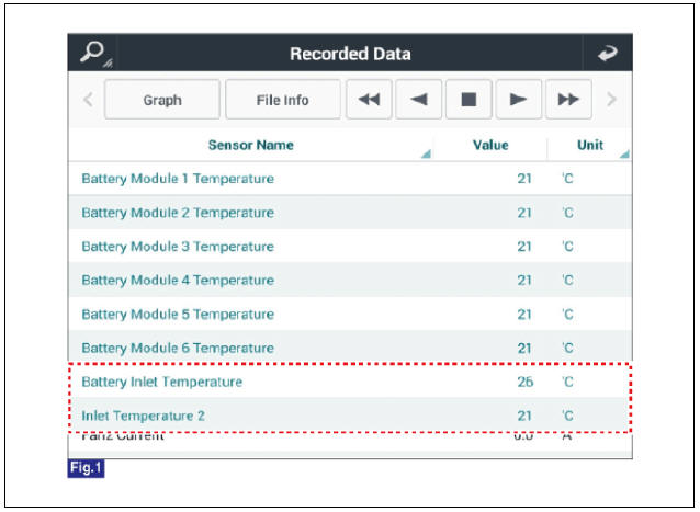
- Check the battery temperature in KDS service data.
- Disconnect the battery temperature signal connector (A).
Main High Voltage Battery Temperature Sensor

Sub High Voltage Battery Temperature Sensor
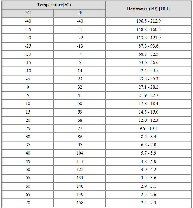
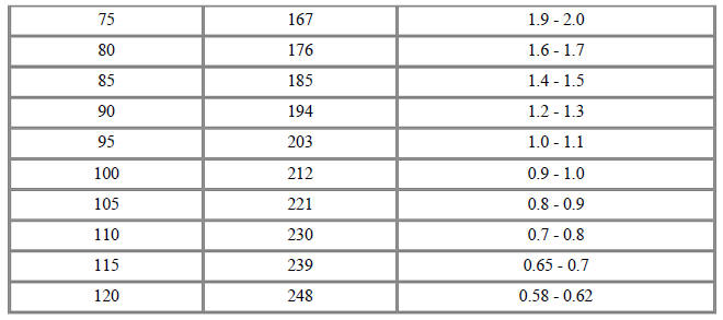
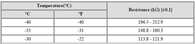
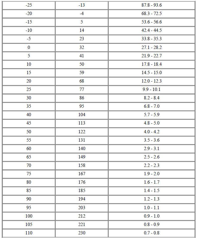
- Measure resistances of the temperature signal terminals (Refer to the table below), then compare the value with the KDS service data.
Specification : Refer to "Specification"
Description
The cell monitoring unit (CMU) is attached to the side of each high voltage
battery module. It
measures the temperature, voltage, VDP of each high voltage battery module and
sends the data to
BMS ECU.
Main High voltage Battery Side

Sub High voltage Battery Side

READ NEXT:
 Cell Monitoring Unit (CMU) Terminal And Input/Output
Signal
Cell Monitoring Unit (CMU) Terminal And Input/Output
Signal
System Configuration
Connector Type
Terminal Function
Cell Monitoring Unit (CMU) #1 (Sub Voltage Battery Pack Assembly)
Connector (B01-A) (16Pin) : High Voltage Battery control
Connector (B01-C) (12Pin) : High Voltage Battery Cel
Sub High Voltage Battery
Removal
Warning
Be sure to read and follow the "General Safety Information and
Caution" before doing any work
related with the high voltage system. Failure to follow the safety
instructions may result in
serious electrical in
Main High Voltage Battery Temperature Sensor
Removal
Warning
Be sure to read and follow the "General Safety Information and
Caution" before doing any work
related with the high voltage system. Failure to follow the safety
instructions may result in
serious electrical in
SEE MORE:
Compression Pressure Inspection
Warning
If the there is lack of power, excessive oil consumption or poor
fuel economy, measure the compression pressure.
Warm up and stop the engine.
Allow the engine to warm up to normal operating temperature.
Remove the air cleaner.
(R
LCD display messages (Kia NIRO Hybrid)
For Plug-in hybrid vehicle (Kia NIRO Hybrid)
LCD displays/ Displayed contents
Door, hood, tailgate, sunroof
open
Low tire pressure warning
display
A: Low tire pressure
A: Lights
1:
2:
3: AUTO
4: OFF (O)
A
Categories
- Home
- KIA Niro EV, Hybrid - Second generation - (SG2) (2021-2024) - Owner's manual
- Kia Niro - First generation - (DE) (2017-2022) - Service and Repair Manual
- Contact Us