KIA Niro: Battery Current Sensor
Specification
Battery Current Sensor
Specification

Description
Battery Current Sensor is integrated into the Power Relay Assembly (PRA) and
measures the current
of the high voltage battery during charging or discharging.

Installation
Warning
- Be sure to read and follow the "General Safety Information and Caution" before doing any work related with the high voltage system. Failure to follow the safety instructions may result in serious electrical injuries.
- Be sure to read and follow the "High Voltage Shut-off Procedures" before doing any work related with the high voltage system. Failure to follow the safety instructions may result in serious electrical injuries.
- Install in the reverse order of removal.
Inspection
Warning
- Be sure to read and follow the "General Safety Information and Caution" before doing any work related with the high voltage system. Failure to follow the safety instructions may result in serious electrical injuries.
- Be sure to read and follow the "High Voltage Shut-off Procedures" before doing any work related with the high voltage system. Failure to follow the safety instructions may result in serious electrical injuries.
- Connect the KDS to the Data Link Connector (DLC).
- Turn the ignition switch ON.
- Check the battery current in KDS service data.

Main Fuse
Specification

Description
The main fuse is mounted in the safety plug and protects the high voltage battery and high voltage circuits from overcurrent.

Main Fuse Repair procedures
Removal
Warning
- Be sure to read and follow the "General Safety Information and Caution" before doing any work related with the high voltage system. Failure to follow the safety instructions may result in serious electrical injuries.
- Be sure to read and follow the "High Voltage Shut-off Procedures" before doing any work related with the high voltage system. Failure to follow the safety instructions may result in serious electrical injuries
- Turn the ignition switch OFF and disconnect the auxiliary 12V battery negative (-) terminal.
- Shut off the high voltage circuit.
(Refer to Hybrid Control System - "High Voltage Shutoff Procedure")
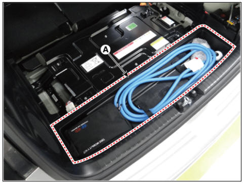
- Remove the center tray trim (A)
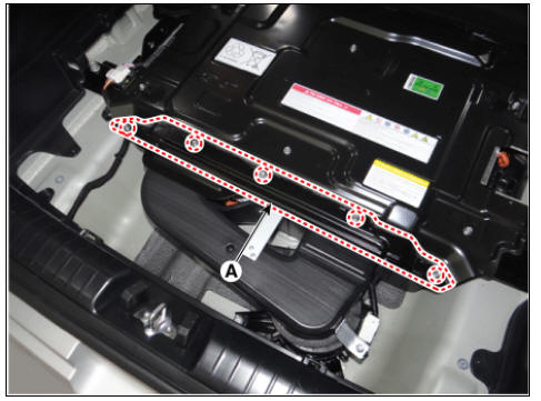
- Remove the sub high voltage battery rear cover (A) after loosening the mounting bolts.
High Voltage Battery Rear Cover mounting bolt : 7.8 - 11.8 N*m (0.8 - 1.2 kgf*m, 5.8 - 8.7 lb*ft)
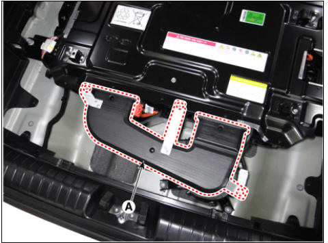
- Remove the rear outlet cooling duct (A) after loosening the mounting bolt.
Rear Outlet Cooling Duct mounting bolt : 7.8 - 11.8 N*m (0.8 - 1.2 kgf*m, 5.8 - 8.7 lb*ft)
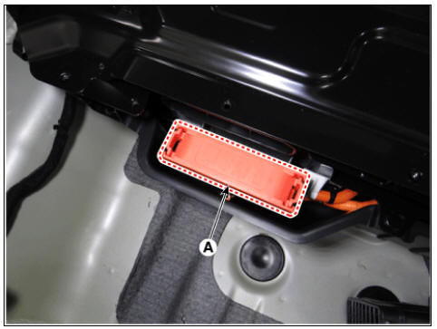
- Remove the main fuse cover (A).
- Remove the main fuse (A) after loosening the mountiong nuts.
Main Fuse mounting nut : 10.98 - 12.94 N*m (1.12 ~ 1.32 kgf*m, 8.10 - 9.55 lb*ft)

Installation
Warning
- Be sure to read and follow the "General Safety Information and Caution" before doing any work related with the high voltage system. Failure to follow the safety instructions may result in serious electrical injuries.
- Be sure to read and follow the "High Voltage Shut-off Procedures" before doing any work related with the high voltage system. Failure to follow the safety instructions may result in serious electrical injuries.
- Install the main fuse in the reverse order of removal.
Warning
Be careful not to miss washers when installing the main fuse.
Inspection
Warning
- Be sure to read and follow the "General Safety Information and Caution" before doing any work related with the high voltage system. Failure to follow the safety instructions may result in serious electrical injuries.
- Be sure to read and follow the "High Voltage Shut-off Procedures" before doing any work related with the high voltage system. Failure to follow the safety instructions may result in serious electrical injuries.
- Remove the main fuse.
(Refer to High Voltage Battery Control System - "Main Fuse")
- Check the continuity between ends of the main fuse.

Specification : 1Ω or less (20ºC (68ºF))
- If the measured resistance is not within the spec value, then exchange the main fuse by following the maintenance guideline.
READ NEXT:
 Battery Temperature Sensor
Specification
Air Inlet Temperature Sensor
Battery Temperature Sensor (Side of cell)
Description
Battery Temperature Sensor is installed inside the high voltage battery pack
assembly. It measures the temperature of t
Cell Monitoring Unit (CMU) Terminal And Input/Output
Signal
System Configuration
Connector Type
Terminal Function
Cell Monitoring Unit (CMU) #1 (Sub Voltage Battery Pack Assembly)
Connector (B01-A) (16Pin) : High Voltage Battery control
Connector (B01-C) (12Pin) : High Voltage Battery Cel
Sub High Voltage Battery
Removal
Warning
Be sure to read and follow the "General Safety Information and
Caution" before doing any work
related with the high voltage system. Failure to follow the safety
instructions may result in
serious electrical in
SEE MORE:
Limitations of Blind-Spot Collision-
Avoidance Assist
Blind-Spot Collision-Avoidance Assist
may not operate properly, or it may
operate unexpectedly under the following
circumstances:
There is inclement weather, such as
heavy snow, heavy rain, etc.
The detecting sensor is covered with
snow,
Replacing headlamp (Low beam/High beam) (Bulb type)
Operation
Before turning off the vehicle, operate
the steering wheel in the opposite
direction of the lamp to be replaced to steer the tires
toward the inside of the
vehicle body.
When replacing the right headlamp:
operate to the
Categories
- Home
- KIA Niro EV, Hybrid - Second generation - (SG2) (2021-2024) - Owner's manual
- Kia Niro - First generation - (DE) (2017-2022) - Service and Repair Manual
- Contact Us