KIA Niro: Piston Pins
- Measure the diameter of the piston pin.
Piston pin diameter : 17.997 - 18.000 mm (0.70854 - 0.70866 in.)
- Measure the piston pin-to-piston clearance.
Piston pin-to-piston clearance : 0.005 - 0.012 mm (0.00020 - 0.00047 in.)
- Check the clearance between the piston pin outer diameter and the connecting rod small end inner diameter.
Piston pin-to-connecting rod clearance : 0.005 - 0.014 mm (0.00002 - 0.00055 in.)
Reassembly
Warning
- Thoroughly clean all parts to be assembled.
- Before installing the parts, apply fresh engine oil to all sliding and rotating surfaces.
- Replace all gaskets, O-rings and oil seals with new parts.
- Always use new crankshaft main bearing cap bolts. Crankshaft main bearing cap bolts are toque-to-yield bolts designed to be permanently elongated beyond the state of elasticity when torqued, so if the bolts are removed and reused, it may cause the bolts to break or fail to maintain clamping force.
- Always use new connecting rod cap bolts. Connecting rod cap bolts are toque-to-yield bolts designed to be permanently elongated beyond the state of elasticity when torqued, so if the bolts are removed and reused, it may cause the bolts to break or fail to maintain clamping force.
- Assemble the piston and the connecting rod.
(1) Install the snap ring (A) in one side of the piston pin hole.

(2) Align the piston front mark (A) and the connecting rod front mark (B).

(3) Insert the piston pin (A) into the piston pin hole and the small end bore of connecting rod.
(4) Install the snap ring (B) to the other side after inserting the piston pin.

Warning
- Apply a sufficient amount of engine oil to outer surface of the piston, inner surface of piston pin hole and small end bore of the connecting rod before inserting the piston pin.
- Be careful not to damage and scratch the small end bore, piston pin hole and piston pin when inserting the piston pin.
- Set the snap ring firmly so that the snap ring can contact with the whole groove of the piston pin hole.
- Install the piston rings.
(1) Install the oil ring spacer and 2 side rails by hand.
(2) Using a piston ring expander, install the 2 compression rings with the maker mark facing upward.
(3) Position the piston rings so that the ring ends are as shown. (The No.1
ring should be on the opposite side of
the No.2 ring.)
Example)

Warning
Confirm that the oil ring turns smoothly.
- Install the connecting rod bearings.
(1) Align the bearing claw with the groove of the connecting rod or connecting rod cap.
(2) Install the bearings (A) in the connecting rod and connecting rod cap (B).

Warning
Be careful not to change the position of bearing caps.
- Install the piston and connecting rod assemblies.
- Before installing the piston, apply a coat of engine oil to the ring grooves and cylinder bores.
- Install the piston and connecting rod assembly with the front marks facing the front of the engine.
(1) Install the ring compressor, check that the rings are securely in place, and then position the piston in the cylinder, and tap it in using the wooden handle of a hammer.

(2) Stop after the ring compressor pops free, and check the connecting rod-to-crank journal alignment before pushing the piston into place.
(3) Apply engine oil to the bolt threads. Install the rod caps with bearings, and tighten the bolts.
Tightening torque : (10.8 - 14.7 N*m (1.1 - 1.5 kgf*m, 8.0 - 10.9 lb*ft)) + (88 - 92º)

Warning
Always use new connecting rod cap bolts. Connecting rod cap bolts
are torque-to-yield bolts designed to
be permanently elongated beyond the state of elasticity when torqued. Reusing
the removed bolts can
cause the bolts to break or fail to maintain clamping force.
- Check the connecting rod end play.
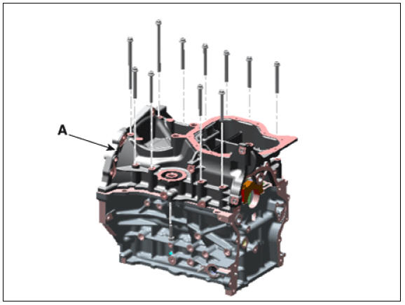
- Install the ladder frame.
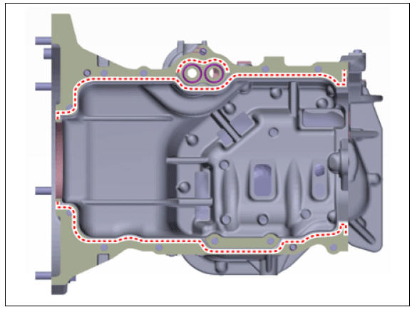
(1) Clean the sealing face before assembling ladder frame and cylinder block.
(2) Install the new O-ring (A) on the cylinder block.

(3) Apply liquid sealant TB 1217H on the oil pan. Assemble the part within 5 minutes of applying sealant.
Bead width :
2.5 mm (0.098 in.) - 3.5 mm (0.138 in.)
- Install the ladder frame (A).
Tightening torque : 18.6 - 23.5 N*m (1.9 - 2.4 kgf*m, 13.7 - 17.4 lb*ft)
- Assemble the remaining parts in the reverse order of disassembly.
READ NEXT:
 Crankshaft Repair procedures
Disassembly
Warning
Be sure to read and follow the "General Safety Information and
Caution" before doing any work related with
the high voltage system. Failure to follow the safety instructions may
result in serious electrical injuries.
Crankshaft
Check the crankshaft bearing oil clearance.
(1) To check main bearing-to-journal oil clearance, remove the lower
crankcase and lower bearings.
(2) Clean each main journal and bearing with a clean shop towel.
(3) Place one strip of plastigag
Crankshaft Bore Identification Mark
Letters are been stamped on the block as a mark for the size of each of the 5
main journal bores.
Use them, and the numbers or bar stamped on the crank (marks for main journal
size), to choose the correct
bearings.
Cylinder Block Specifi
SEE MORE:
Warning and indicator
lights
Ready indicator READY
This indicator appears:
When the vehicle is ready to be driven.
ON: Normal driving is possible.
OFF: Normal driving is not possible, or
a problem has occurred.
Blinking: Emergency driving.
When the ready indicator
Engine Mounting Repair Procedures
Engine Mounting Components and components location
Transaxle mounting bracket
Roll rod bracket
Engine mounting bracket
Engine mounting support bracket
Engine Mounting Repair Procedures
Removal and
Installation
Engine Mounting Brac
Categories
- Home
- KIA Niro EV, Hybrid - Second generation - (SG2) (2021-2024) - Owner's manual
- Kia Niro - First generation - (DE) (2017-2022) - Service and Repair Manual
- Contact Us