KIA Niro: Crankshaft Bore Identification Mark

Letters are been stamped on the block as a mark for the size of each of the 5 main journal bores.
Use them, and the numbers or bar stamped on the crank (marks for main journal size), to choose the correct bearings.
Cylinder Block Specifications
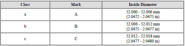
Crankshaft Journal Identification Mark

Warning
Conform to the stamping order in the direction of the arrow from #1.
Crankshaft Specifications

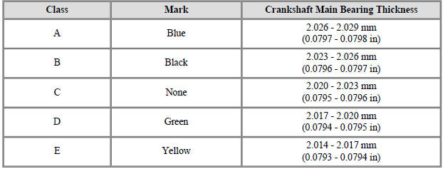
Crankshaft Bearing Identification Mark

Crankshaft Bearing Specifications
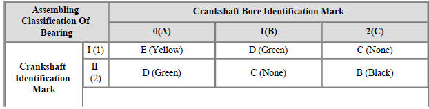
(9) Select a crankshaft bearing using the selection chart.
Selection Chart For Crankshaft Bearings

- Check crankshaft end play.
Using a dial indicator, measure the thrust clearance while prying the crankshaft back and forth with a screwdriver.
If the end play is greater than maximum, replace the center bearing.
End play
Standard: 0.07 - 0.25 mm (0.0028 - 0.0098 in.)
- Inspect main journals and crank pins.
Using a micrometer, measure the diameter of each main journal and crank pin.
Main journal diameter :
47.942 - 47.960- mm (1.88748 - 1.88819 in.)
Crank pin diameter :
68.954 - 38.972 mm (1.53362 - 1.53433 in.)

Crankshaft - Reassembly
Warning
- Thoroughly clean all parts to be assembled.
- Before installing the parts, apply fresh engine oil to all sliding and rotating surfaces.
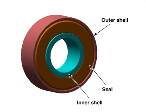
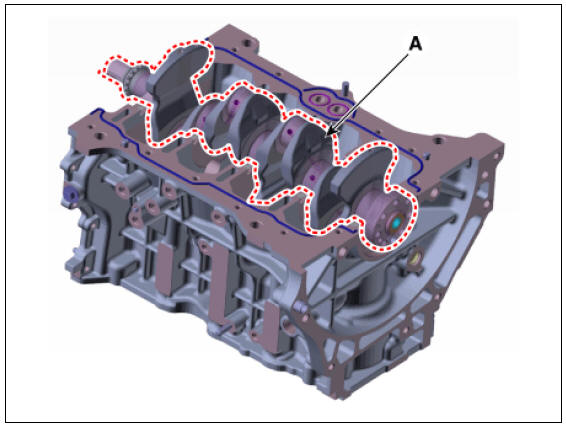
- Check if the pilot bearing (A) is installed in the crankshaft when
replacing the crankshaft or short engine.
If being not installed, be sure to install the pilot bearing (A).

Warning
- Be sure to replace the crankshaft and pilot bearing together, because crankshaft can be damaged or deformed when removing the pilot bearing.
- Be sure to force on only outer shell of pilot bearing because
when forcing on the pilot bearing seal or inner
shell, it can be damaged.
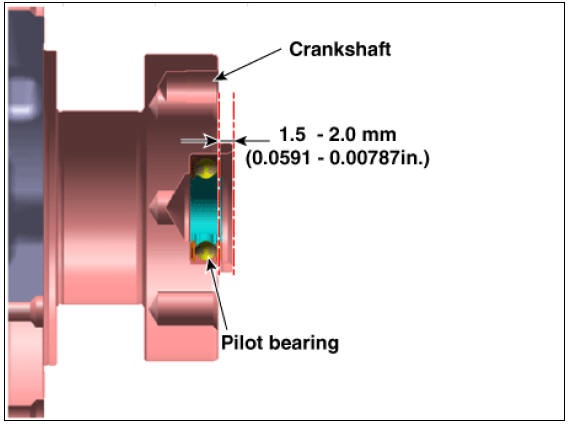
- Install the pilot bearing to the crank shaft as the illustration below.
Press force :
180 - 920 N (18 - 94 kgf , 40 - 206 lbf)
Press depth :
1.5 - 2.0 mm (0.0591 - 0.0787 in.)
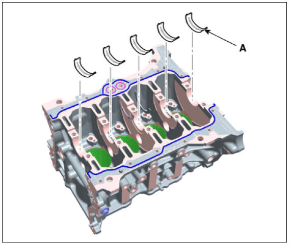
- Install the crankshaft main bearings.
Warning
There is an oil groove for oil holes on upper bearing but not on lower bearing.
(1) Align the bearing claw with the groove of the cylinder block, and push in the 5 upper bearings (A).
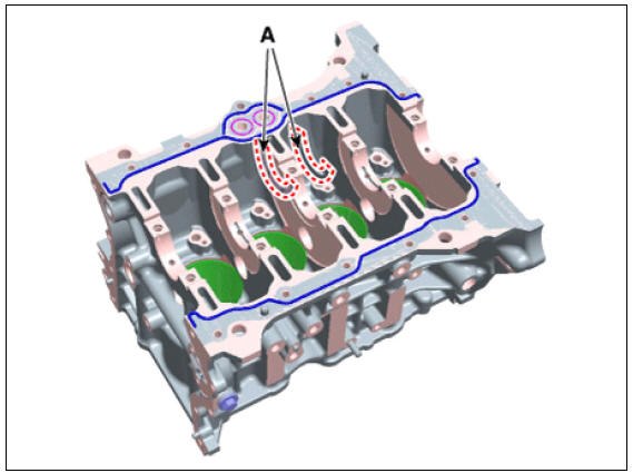
- Install the thrust bearings.
Install the 2 thrust bearings (A) on both sides of the No.3 journal of the cylinder block with the oil groove facing out.
- Place the crankshaft (A) on the cylinder block.
- Install the main bearing caps and tighten the cap bolts.
(1) Apply a light coat of engine oil on the threads of the bolts. Tighten all the bolts with the specified torque in numerical order first, then tighten all the bolts with the specified angle in numerical order.
Tightening torque : (17.7 - 21.6 N*m (1.8 - 2.2 kgf*m, 13.0 - 15.9 lb*ft)) + (88 - 92º)

Warning
- Always use new crankshaft main bearing cap bolts. Crankshaft main bearing cap bolts are torque - to - yield bolts designed to be permanently elongated beyond the state of elasticity when torqued, so if the bolts are removed and reused, it may cause the bolts to break or fail to maintain clamping force.
- Be sure to assemble the main bearing caps in correct order.
- Install the main bearing cap with the arrow facing the front of the engine.
- Tighten all the main bearing cap bolts with the specified torque first, and then retighten all the bolts with the specified angle.
(2) Check that the crankshaft turns smoothly.
- Check the crankshaft end play.
- Install the other parts in the reverse order of disassembly.
Warning
In case the crankshaft is replaced with a new one, select the proper connecting rod bearing according to the pin journal mark on the crankshaft.
- Connecting rod bearing selection (Refer to Cylinder Block Assembly - "Piston and Connecting Rod")
READ NEXT:
 Cylinder Block Repair procedures
Warning
Be sure to read and follow the "General Safety Information and
Caution" before doing any work related
with the high voltage system. Failure to follow the safety instructions may
result in serious electrical
injuries.
Be sure t
Cylinder Head Cover Components and components location | Cylinder Head Cover Repair procedures
Components
Camshaft bearing cap
Camshaft front bearing cap
Exhaust camshaft
Intake camshaft
Exhaust CVVT assembly
Intake CVVT assembly
Cylinder head
Cylinder head gasket
Retainer lock
Retainer
SEE MORE:
Right remote control switch (Cruise control
switch)
Right remote control switch (Cruise control
switch)
Circuit Diagram
Right remote control switch Repair Procedures
Removal
Remove the steering wheel remote controller. (RH)
(Refer to Body Electrical System - "AVN Remote Co
Passenger's front air bag ON/OFF settings (Kia NIRO Hybrid)
You can deactivate the passenger's front
air bag from the User Settings Mode on
the LCD display if a child restraint is
installed on the front passenger's seat or
if the front passenger's seat is unoccupied
by a person. If your vehic
Categories
- Home
- KIA Niro EV, Hybrid - Second generation - (SG2) (2021-2024) - Owner's manual
- Kia Niro - First generation - (DE) (2017-2022) - Service and Repair Manual
- Contact Us