KIA Niro: Knock Sensor (KS)
Specification

Knock Sensor (KS) Description and operation
Description
Knocking is a phenomenon characterized by undesirable vibration and noise
that can cause engine
damage. Knock Sensor (KS) is installed on the cylinder block and senses engine
knocking.
When knocking occurs, the vibration from the cylinder block is applied as pressure to the piezoelectric element, and the sensor produces voltage signal to ECM. On receipt of this signal, ECM will control the ignition timing by retarding the ignition timing and then advancing the ignition timing when the knocking disappears. This sequential control can improve engine power, torque and fuel economy.

Circuit Diagram

Harness Connector

Knock Sensor (KS) Repair procedures
Removal
- Switch "OFF" the ignition and disconnect the negative (-) battery terminal.
- Remove the intake manifold.
(Refer to Engine Mechanical System - "Intanke Manifold")
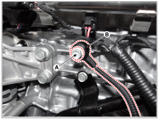
- Remove the installation bolt (A), and then remove the sensor (B) from the cylinder block.
Knock sensor mounting bolt: 18.6 - 23.5 N*m (1.9 - 2.4 kgf*m, 13.7 - 17.4 lb*ft)

Installation
Warning
- Install the component to the specified torque.
- Note that internal damage may occur when the component is dropped. If the component has been dropped, inspect before installing.
- Install in the reverse order of removal.
READ NEXT:
 Heated Oxygen Sensor (HO2S)
Specification
HO2S (Bank 1/Sensor 1) (Linear)
HO2S (Bank 1/Sensor 2) (Binary type)
Description
Heated Oxygen Sensor (HO2S), consisting of zirconium and alumina, is
installed on both upstream
and downstream of the Manifold Catalytic Con
Rail Pressure Sensor (RPS)
Specification
Rail Pressure Sensor (RPS) Description and operation
Description
Installed on the delivery pipe, the Rail Pressure Sensor (RPS) measures the
instantaneous fuel pressure
in the delivery pipe. The sensing element (Semiconduc
Accelerator Position Sensor (APS)
Specification
Accelerator Position Sensor (APS) Description and operation
Description
Installed on the accelerator pedal module, the Accelerator Position Sensor (APS)
detects the rotation
angle of the accelerator pedal. The APS is one o
SEE MORE:
Navigation-based Smart Cruise Control operation
Operating conditions
Navigation-based Smart Cruise Control
is ready to operate if all of the following
conditions are satisfied:
Smart Cruise Control is operating
Driving on main roads of highways (or
motorways)
NOTICE
For more details
Before Troubleshooting
Check applicable fuses in the appropriate fuse/relay box.
Check the battery for damage, state of charge, cleanliness and tight
connections.
(Refer to Engine Electrical System - "Battery")
Warning
Do not quick-charge a batte
Categories
- Home
- KIA Niro EV, Hybrid - Second generation - (SG2) (2021-2024) - Owner's manual
- Kia Niro - First generation - (DE) (2017-2022) - Service and Repair Manual
- Contact Us