KIA Niro: Rail Pressure Sensor (RPS)
Specification
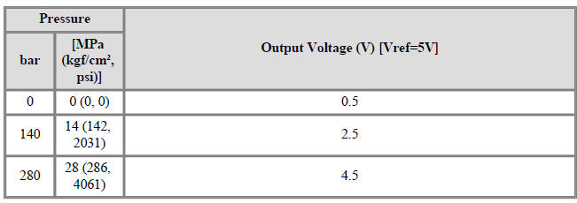

Rail Pressure Sensor (RPS) Description and operation
Description
Installed on the delivery pipe, the Rail Pressure Sensor (RPS) measures the
instantaneous fuel pressure
in the delivery pipe. The sensing element (Semiconductor element) built in the
sensor converts the
pressure to voltage signal. By using this signal, the ECM can control correct
injection amount and
timing and adjusts the fuel pressure with the fuel pressure regulator valve if
the target pressure is
different from the actual pressure calculated by the RPS output signal.

Circuit Diagram

Harness Connector

Rail Pressure Sensor (RPS) Repair procedures
Inspection
- Connect the KDS on the Data Link Connector (DLC).
- Measure the output voltage of the RPS during idle at various engine speeds.

Removal
- Release the residual pressure in fuel line.
(Refer to Fuel Delivery System - "Release Residual Pressure in Fuel Line").
- Switch "OFF" the ignition and disconnect the negative (-) battery terminal.
- Remove the intake manifold.
(Refer to Engine Mechanical System - "Intake Manifold")
- Remove the injector foam (A).
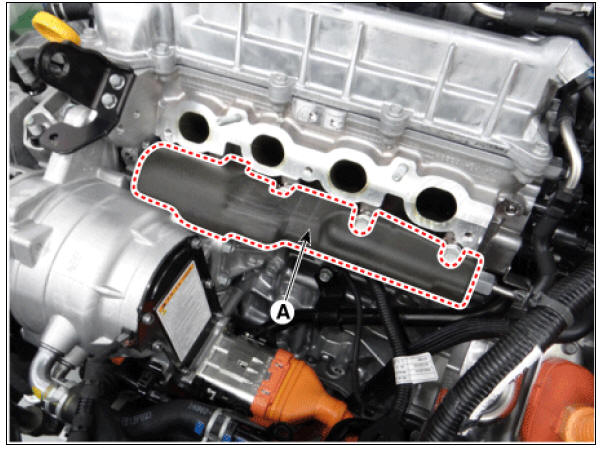
- Disconnect the rail pressure sensor connector (A), and then remove the sensor (B) from the delivery pipe.
Rail Pressure Sensor : 30.0 - 34.3 N*m (3.0 - 3.5 kgf*m, 22.1 - 25.3 lb*ft)

Installation
Warning
- Install the component to the specified torque.
- Note that internal damage may occur when the component is dropped. If the component has been dropped, inspect before installing.
- Install in the reverse order of removal.
Signal Waveform
 БЮ
Fig.2) Nomal signal waveform of rail pressure sensor at engine idle.
БЮ
Fig.2) Nomal signal waveform of rail pressure sensor at engine idle.
READ NEXT:
 Accelerator Position Sensor (APS)
Specification
Accelerator Position Sensor (APS) Description and operation
Description
Installed on the accelerator pedal module, the Accelerator Position Sensor (APS)
detects the rotation
angle of the accelerator pedal. The APS is one o
Injector
Specification
Description
The GDI injector is similar to a standard injector, but sprays fuel at a much
higher pressure directly
into the combustion chamber and has a swirl disc to get the fuel swirling as it
exits the nozzle. This
aids i
Purge Control Solenoid Valve (PCSV)
Specification
Purge Control Solenoid Valve (PCSV) Description and operation
Description
Installed on the intake manifold, the Purge Control Solenoid Valve (PCSV)
controls the evaporative
purge between the canister and the intake manifold. I
SEE MORE:
Button Engine Start System / Description And Operation
Button Engine Start System / Components And Components Location
Body control module (BCM)
Smart key unit (SMK)
Interior antenna 1
Interior antenna 2
FOB key
Start Stop Button (SSB)
Door handle & door antenna
Bumper ant
Engine Oil Repair procedures
Warning
Prolonged and repeated contact with mineral oil will result in
the removal of natural fats from the skin, leading to
dryness, irritation and dermatitis. In addition, used engine oil contains
potentially harmful contaminants which
Categories
- Home
- KIA Niro EV, Hybrid - Second generation - (SG2) (2021-2024) - Owner's manual
- Kia Niro - First generation - (DE) (2017-2022) - Service and Repair Manual
- Contact Us