KIA Niro: Accelerator Position Sensor (APS)
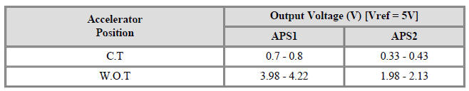
Specification

Accelerator Position Sensor (APS) Description and operation
Description
Installed on the accelerator pedal module, the Accelerator Position Sensor (APS)
detects the rotation
angle of the accelerator pedal. The APS is one of the most important sensors in
engine control system.
Therefore, each of the two sensors comprising the APS has individual power and
ground line. The
second sensor monitors the first and its output voltage is half the first one.
If the ratio of the sensors 1
and 2 is out of the range (approximately 1/2), the diagnostic system judges that
it is abnormal.

Circuit Diagram

Harness Connector

Inspection
- Connect the KDS on the Data Link Connector (DLC).
- Switch "ON" the ignition.
- Measure the output voltage of the APS 1 and 2 at C.T and W.O.T.

Accelerator Position Sensor (APS) Repair procedures
Removal
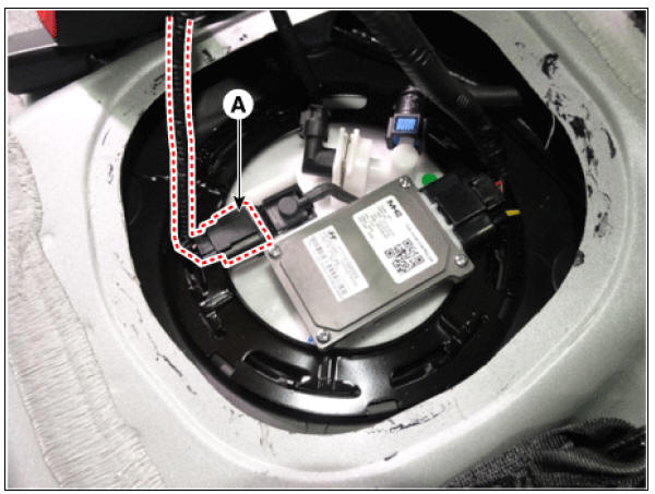
- Switch "OFF" the ignition and disconnect the negative (-) battery terminal.
- Disconnect the accelerator position sensor connector (A).
- Remove the accelerator position sensor after loosening the mounting nuts (B).
Accelerator pedal sensor mounting nut : 12.7 - 15.7 N*m (1.3 - 1.6 kgf*m, 9.4 - 10.6 lb*ft)

Installation
- Install in the reverse order of removal.
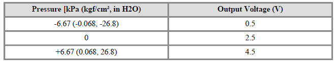
Specification

Fuel Tank Pressure Sensor (FTPS)
Description
Fuel Tank Pressure Sensor (FTPS) is a component of the evaporative emission
control system and is
installed on the fuel tank, the fuel pump, or the canister. It checks the purge
control solenoid valve
operation and detects a leakage of the system.

Circuit Diagram

Harness Connector

Inspection
- Connect the KDS on the Data Link Connector (DLC).
- Measure the output voltage of the FTPS.
Specification : Refer to "Specification"
Fuel Tank Pressure Sensor (FTPS)
Removal
- Turn the ignition switch OFF and disconnect the battery negative (-) cable.
- Remove the rear seat cushion.
(Refer to Body - "Rear Seat Assembly")
- Remove the fuel pump service cover (A).

Warning
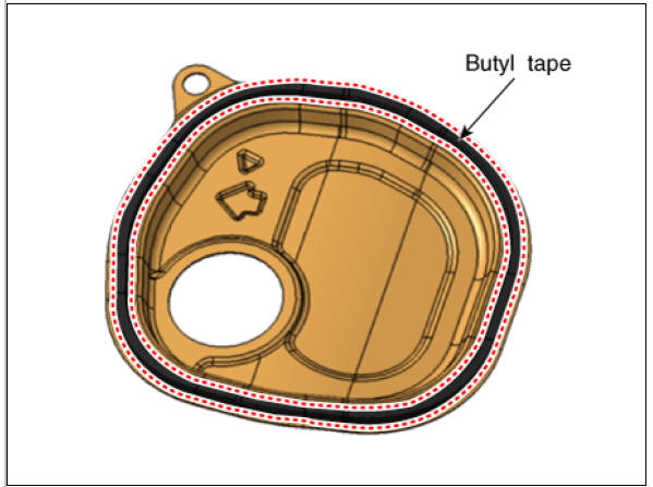
- When reinstalling a protective cover for a fuel pump, remove the existing butyl tape and apply a new one.
- Before assembling the protective cover, ensure that the
temperature of the butyl is about 30ºC using a
hair dryer or a heat gun.
Warning
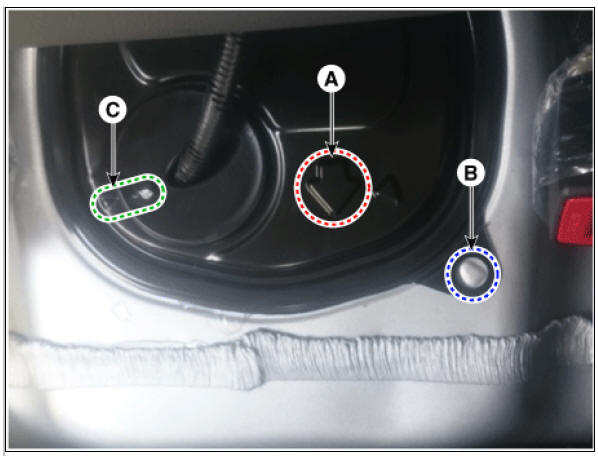
When installing the protective cover for the fuel pump, pay attention to the installation direction of the grommet and the protective cover.
- The arrow (A) should be in the forward direction of the car.
- Align the bulging part of the vehicle body (B) with the hole of the protective cover.
- Align the bulging part of the grommet (C) with the bulging part
of the protective cover.
- Disconnect the fuel tank pressure sensor connector (A).
- Remove the fuel tank pressure sensor (B) after releasing the hooks vertically.

Installation
Warning
- Install the component with the specified torques.
- Note that internal damage may occur when the component is dropped. In this case, use it after inspecting.
Warning
- Insert the sensor in the installation hole and be careful not to damage when installation.
- Install in the reverse order of removal.
READ NEXT:
 Injector
Specification
Description
The GDI injector is similar to a standard injector, but sprays fuel at a much
higher pressure directly
into the combustion chamber and has a swirl disc to get the fuel swirling as it
exits the nozzle. This
aids i
Purge Control Solenoid Valve (PCSV)
Specification
Purge Control Solenoid Valve (PCSV) Description and operation
Description
Installed on the intake manifold, the Purge Control Solenoid Valve (PCSV)
controls the evaporative
purge between the canister and the intake manifold. I
Variable Force Solenoid (VFS)
Description
Continuous Variable Valve Timing (CVVT) system advances or retards the valve
timing of the intake
and exhaust valve in accordance with the ECM control signal which is calculated
by the engine speed
and load.By controlling CVVT, the
SEE MORE:
Lane Following Assist operation
Turning Lane Following Assist On/Off
With the engine on, shortly press the
Lane Driving Assist button located on
the steering wheel to turn on Lane Following
Assist. The grey or green ( )
indicator light will appear on the cluster.
Press
Filter inspection
The climate control air filter should be replaced according to the
maintenance schedule.
If the vehicle is operated in severely air-polluted cities or on dusty rough
roads for a long period, it
should be inspected more frequently and replaced
Categories
- Home
- KIA Niro EV, Hybrid - Second generation - (SG2) (2021-2024) - Owner's manual
- Kia Niro - First generation - (DE) (2017-2022) - Service and Repair Manual
- Contact Us