KIA Niro: Heated Oxygen Sensor (HO2S)
Specification
HO2S (Bank 1/Sensor 1) (Linear)

HO2S (Bank 1/Sensor 2) (Binary type)

Description
Heated Oxygen Sensor (HO2S), consisting of zirconium and alumina, is
installed on both upstream
and downstream of the Manifold Catalytic Converter (MCC) to detect the air/fuel
ratio and send it to
the ECM. The sensor output voltage varies in accordance with the air/fuel ratio.
The sensor must be hot in order to operate normally. To keep it hot, the sensor
has a heater which is
controlled by the ECM via a duty cycle signal. When the exhaust gas temperature
is lower than the
specified value, the heater warms the sensor tip.
Inspection
- Switch "OFF" the ignition.
- Disconnect the HO2S connector.
- Measure resistance between the HO2S terminals 4 and 5 (B1/S1).
Specification: 2.5 - 4.0Ω (20ºC(68ºF))
- Measure resistance between the HO2S terminals 3 and 4 (B1/S2).
Specification: Approx. 9.0 Ω (21ºC(69.8ºF))
- Check that the resistance is within the specification.
Removal
Warning
Note that the SST (Part No.: 09392-1Y100 or 09392-2H100) can be used for removing the heated oxygen sensor.
Bank 1 / Sensor 1
- Switch "OFF" the ignition and disconnect the negative (-) battery terminal.
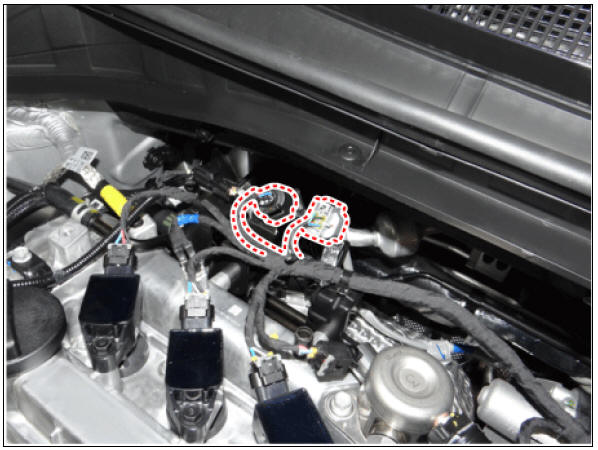
- Disconnect the connector (A), and then remove the sensor (B).
Heated oxygen sensor : 39.2 - 49.1 N*m (4.0 - 5.0 kgf*m, 28.9 - 36.2 lb*ft)

Bank 1 / Sensor 2
- Switch "OFF" the ignition and disconnect the negative (-) battery terminal.
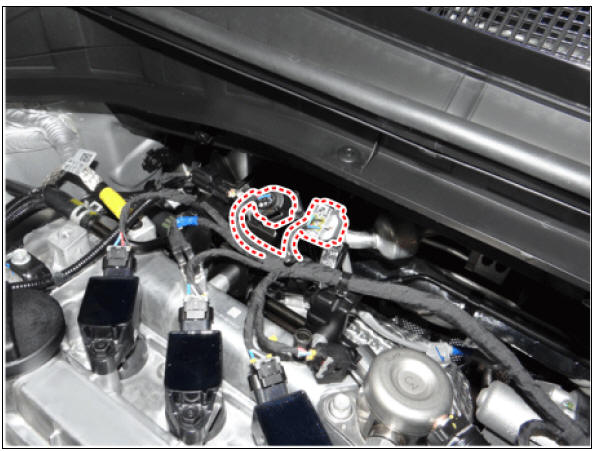
- Disconnect the connector (A), and then remove the sensor (B).
Heated oxygen sensor : 39.2 - 49.1 N*m (4.0 - 5.0 kgf*m, 28.9 - 36.2 lb*ft)

Installation
Warning
- Install the component to the specified torque.
- Note that internal damage may occur when the component is dropped. If the component has been dropped, inspect before installing.
Warning
- Keep the sensing element and connector free from cleaner, spray or grease as oil substance may cause the sensor to malfunction.
- Sensor and its wiring may get damaged from contact with the exhaust system (e.g. Exhaust Manifold, Catalytic Converter).
- Install in the reverse order of removal.
Description
Installed in exhaust manifold, the Exhaust Gas Temperature Sensor (EGTS) #1
for EWGA senses the
temperature of exhaust gas flowing into the EWGA.
Installed in Gasoline Particulate Filter (GPF) assembly, the Exhaust Gas Temperature Sensor (EGTS) #2 for DPF senses the temperature of exhaust gas flowing into the GPF.
When predetermined engine condition is met, ECM burns soot collected in DPF with exhaust gas.
During this, the exhaust gas temperature is an important factor of engine condition.
Specification
Exhaust Gas Temperature Sensor (EGTS) #1, 2
- Type : Thermistor type
Circuit Diagram
EGTS #1

Harness Connector

EGTS #2

Harness Connector

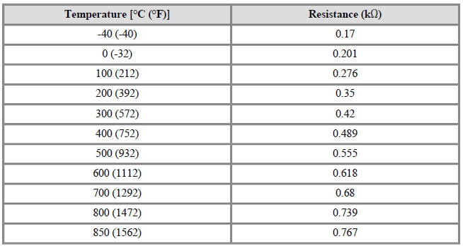
Inspection
- Turn ignition switch OFF.
- Disconnect the connector of exhaust gas temperature sensors #1/#2.
- Measure resistance between sensor signal terminal and ground terminal.
- Check that the resistance is within the specification.
Exhaust Gas Temperature Sensor (EGTS #1, #2 (T3, T4))

Removal
EGTS #1 (T3)
- Turn the ignition switch OFF and disconnect the battery negative (-) terminal.
- Lift the vehicle.
- Disconnect the EGTS #1 connector (A).
- Remove the EGTS #1 (B).

EGTS #2 (T4)
- Turn the ignition switch OFF and disconnect the battery negative (-) terminal.
- Lift the vehicle.
- Disconnect the EGTS #2 connector (A).
- Remove the EGTS #2 (B).

Installation
Warning
- Install the component to the specified torques.
- Note that internal damage may occur when the component is dropped. In this case, use it after inspecting.
- Install in the reverse order of removal.
READ NEXT:
 Rail Pressure Sensor (RPS)
Specification
Rail Pressure Sensor (RPS) Description and operation
Description
Installed on the delivery pipe, the Rail Pressure Sensor (RPS) measures the
instantaneous fuel pressure
in the delivery pipe. The sensing element (Semiconduc
Accelerator Position Sensor (APS)
Specification
Accelerator Position Sensor (APS) Description and operation
Description
Installed on the accelerator pedal module, the Accelerator Position Sensor (APS)
detects the rotation
angle of the accelerator pedal. The APS is one o
Injector
Specification
Description
The GDI injector is similar to a standard injector, but sprays fuel at a much
higher pressure directly
into the combustion chamber and has a swirl disc to get the fuel swirling as it
exits the nozzle. This
aids i
SEE MORE:
DC Fuse
Component Location
DC Fuse
Inverter Connector (↔ Power Relay Assembly (PRA))
Inverter Connector (↔ Electric A/C compressor)
Component Location
Harness Connector
DC Fuse Repair procedures
Removal
Warning
Be sure to rea
Hybrid Motor Control System
Description
The Hybrid Power Control Unit (HPCU), composed of various components, is
the core device among the Power Electronics
devices that acts as the brain.
It comprises of the Hybrid Control Unit (HCU), an inverter Motor Control
Un
Categories
- Home
- KIA Niro EV, Hybrid - Second generation - (SG2) (2021-2024) - Owner's manual
- Kia Niro - First generation - (DE) (2017-2022) - Service and Repair Manual
- Contact Us