KIA Niro: Inlet Temperature Sensor
Inlet Temperature Sensor #1 (Main High Voltage)
Description
The inlet temperature sensor is installed on top of the high voltage battery module, and it detects the air temperature inside the battery system assembly.
The inlet temperature sensor value determines the cooling fan operation status.
Inlet Temperature Sensor #1 (Main High Voltage)

Inlet Temperature Sensor #2 (Sub High Voltage)

Circuit Diagram

Removal
Warning
- Be sure to read and follow the "General Safety Information and Caution" before doing any work related with the high voltage system. Failure to follow the safety instructions may result in serious electrical injuries.
- Be sure to read and follow the "High Voltage Shut-off Procedures" before doing any work related with the high voltage system. Failure to follow the safety instructions may result in serious electrical injuries.
Inlet Temperature Sensor #1
- Shut off the high voltage circuit.
(Refer to Hybrid Control System - "High Voltage Shutoff Procedure")
- Remove the rear seat cushion.
(Refer to Body - "Rear Seat Assembly")
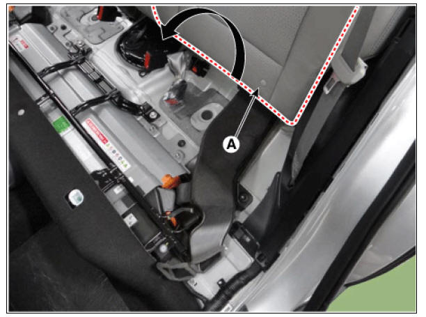
- Remove the rear door scuff trim (A).
(Refer to Body - "Rear Door Scuff Trim")
- Remove the inlet duct.
(Refer to High Voltage Battery Cooling System - "Cooling Duct")
- Open the rear seat back (A) in the direction of an arrow.
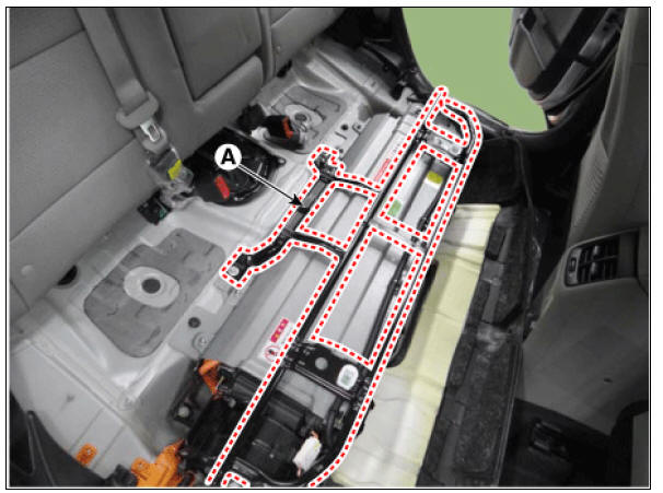
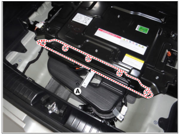
- Remove the upper frame (A) after loosening the mounting bolts and nuts.
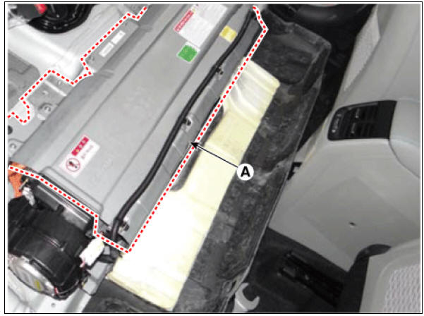
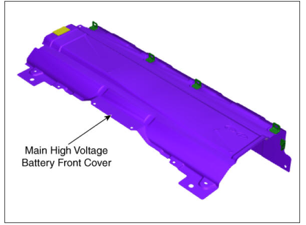
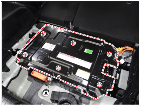
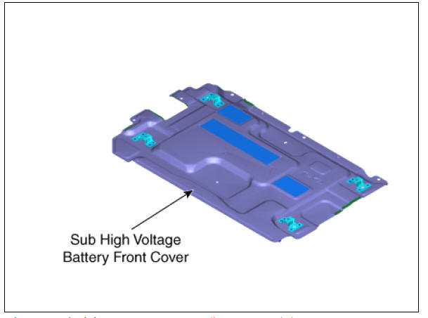
- Remove the high voltage battery front cover (A).
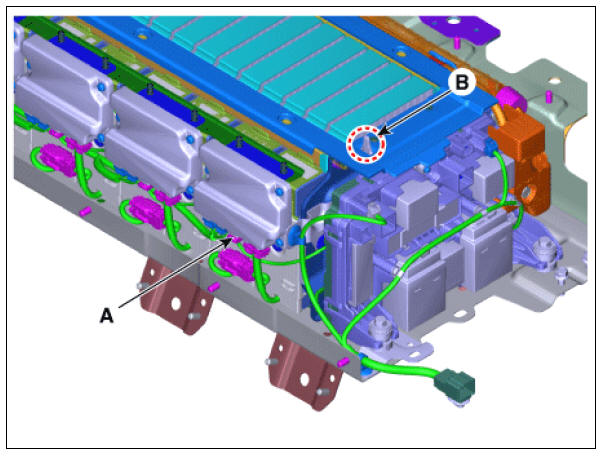
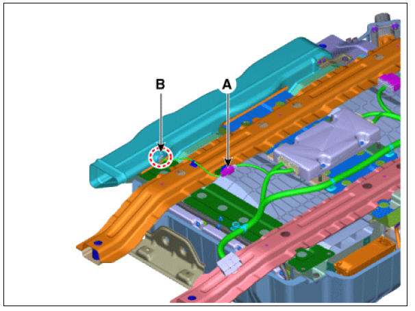
- Disconnect the inlet temperature sensor #1 connector (A).
- Remove the inlet temperature sensor #1 (B).
Inlet Temperature Sensor #2
- Switch "OFF" the ignition and disconnect the negative (-) terminal of the auxiliary 12V battery.
- Shut off the high voltage circuit.
(Refer to Hybrid Control System - "High Voltage Shutoff Procedure")
- Remove the sub high voltage battery rear cover (A) after loosening the mounting bolts.
Sub High Voltage Battery Rear Cover mounting bolt : 7.8 - 11.8 N*m (0.8 - 1.2 kgf*m, 5.8 - 8.7 lb*ft)
- Remove the sub high voltage battery cover (A) after loosening the mounting bolts.
- Disconnect the inlet temperature sensor #2 connector (A).
- Remove the inlet temperature sensor #2 (B).
Inspection
Warning
- Be sure to read and follow the "General Safety Information and Caution" before doing any work related with the high voltage system. Failure to follow the safety instructions may result in serious electrical injuries.
- Be sure to read and follow the "High Voltage Shut-off Procedures" before doing any work related with the high voltage system. Failure to follow the safety instructions may result in serious electrical injuries.
- Turn ignition switch OFF and disconnect the negative (-) battery cable.
- Shut off the high voltage.
(Refer to "High voltage Shut-off Procedures")
- Disconnect the inlet temperature sensor connector.
- Measure resistance between the sensor terminals.
- Check that the resistance is within the specification.
Specification
Installation
Warning
- Be sure to read and follow the "General Safety Information and Caution" before doing any work related with the high voltage system. Failure to follow the safety instructions may result in serious electrical injuries.
- Be sure to read and follow the "High Voltage Shut-off Procedures" before doing any work related with the high voltage system. Failure to follow the safety instructions may result in serious electrical injuries.
- Install in the reverse order of removal.
READ NEXT:
 Low Voltage DC/DC Converter
Specification
Description
The Low Voltage DC/DC is integrated into the HPCU. It charges the auxiliary
battery as a substitute
for generator by converting the high voltage (DC 270V) from the high voltage
battery into low voltage
(DC 12V).
Power Cable
Components
Power Cable (HPCU↔Main High Voltage Battery
System)
Power Cable (HPCU↔HSG, Electric /C Compressor)
Power Cable (Main High Voltage Battery System ↔ Sub
High Voltage Battery System)
Removal
Warning
Be sure to re
Power Cable (HPCU-HSG, Electric /C Compressor). Main High Voltage Battery System, Sub High Voltage Battery System
Turn ignition switch OFF and disconnect the negative (-) battery cable.
Shut off the high voltage.
(Refer to "High voltage Shut-off Procedures")
Disconnect the motor power cable connector (A) and HSG p
SEE MORE:
Multifunction Switch
Specifications
Multifunction Switch / Components And Components Location
Steering column shaft
Lighting switch
Wiper/Washer switch
Screws
Clock spring
LHD
RHD
Multifunction Switch / Repair Procedures
Removal
Disconn
Power Door Lock Module Repair procedures
Inspection
Warning
When removing with a flat-tip screwdriver or remover, wrap
protective tape around the tools to
prevent damage to components.
When removing the interior trim pieces, use a plastic panel
removal tool not to damage the
Categories
- Home
- KIA Niro EV, Hybrid - Second generation - (SG2) (2021-2024) - Owner's manual
- Kia Niro - First generation - (DE) (2017-2022) - Service and Repair Manual
- Contact Us