KIA Niro: Power Cable
Components
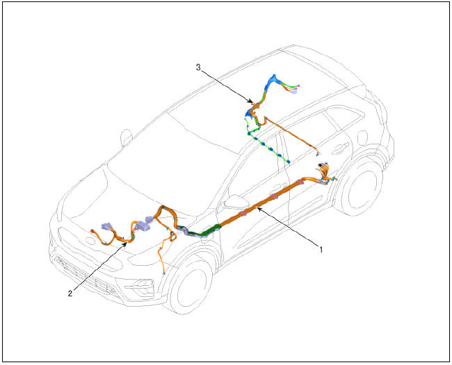
- Power Cable (HPCU↔Main High Voltage Battery System)
- Power Cable (HPCU↔HSG, Electric /C Compressor)
- Power Cable (Main High Voltage Battery System ↔ Sub High Voltage Battery System)
Removal
Warning
- Be sure to read and follow the "General Safety Information and Caution" before doing any work related with the high voltage system. Failure to follow the safety instructions may result in serious electrical injuries.
- Be sure to read and follow the "High Voltage Shut-off
Procedures" before doing any work related with the high voltage system.
Failure to follow the safety instructions may result in serious electrical injuries.
Engine Room Fuse & Relay Box, HPCU ↔ Auxiliary 12V Battery & High Voltage Battery System Assembly
- Shut off the high voltage circuit.
(Refer to Hybrid Control System - "High Voltage Shutoff Procedure")
- Remove the air cleaner assembly.
(Refer to Engine Mechanical System - "Air Cleaner")
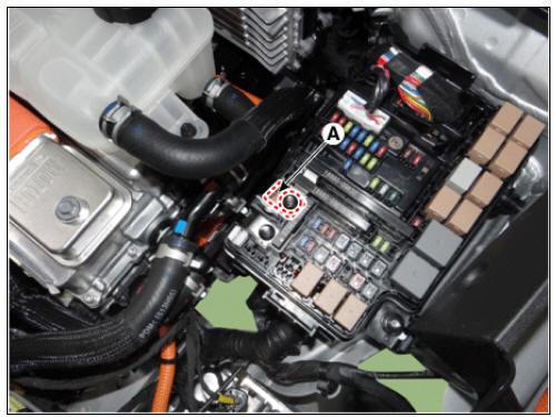
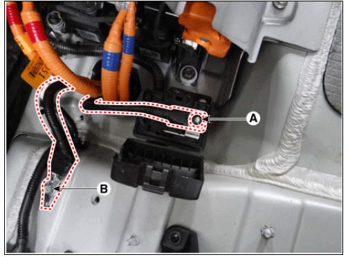
- Disconnect the power cable (A) from the HPCU.

Warning
Remove the inverter power cale in the follwing order.
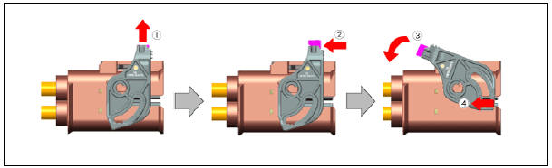
- Disconnect the clamp (A).

Auxiliary 12V battery (+) cable mounting nut (Engine room fuse & relay box)
:
10.8 - 13.7 N*m (1.1 - 1.4 kgf*m, 8.0 - 10.1 lb*ft)
- Remove the high voltage battery rear cover.
(Refer to High Voltage Battery System - "Case")
- Remove the high voltage inlet duct.
(Refer to High Voltage Battery Cooling System - "Cooling Duct")
- Disconnect the inverter power (+) (A) , inverter power (+) (B), OBC power connector (+) (C) and OBC power connector (-) (D)
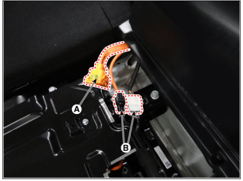
- Disconnect the auxiliary 12V battery positive (+) cable after loosening the mounting nut (A).
- Disconnect the ground cable after loosening the mounting bolt (B).
Ground cable mounting bolt (M6) (Trunk chassis ground) : 10.8 - 13.7 N*m (1.1 - 1.4 kgf*m, 8.0 - 10.1 lb*ft)
- Lift the vehicle.
- Remove the front sub frame.
(Refer to Suspension System - "Sub Frame")
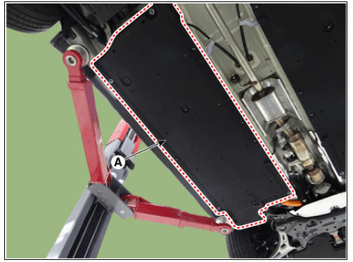
- Remove the side under cover (A) after loosening the mounting bolts and nuts.
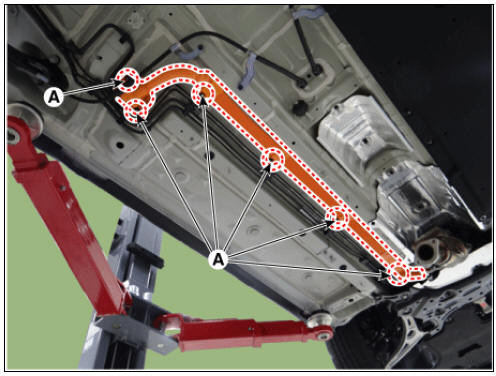
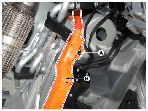
- Remove the power cable (B) after loosening the mounting nuts (A).
Power cable mounting nut : 10.8 - 13.7 N*m (1.1 - 1.4 kgf*m, 8.0 - 10.1 lb*ft)

READ NEXT:
 Power Cable (HPCU-HSG, Electric /C Compressor). Main High Voltage Battery System, Sub High Voltage Battery System
Turn ignition switch OFF and disconnect the negative (-) battery cable.
Shut off the high voltage.
(Refer to "High voltage Shut-off Procedures")
Disconnect the motor power cable connector (A) and HSG p
ON-Board Charger (OBC)
HPCU (Hybrid Power Control Unit)
ON-Board Charger (OBC)
Normal Chage Port
Power Cable (HPCU↔HSG, Electric /C Compressor)
Power Cable (HPCU↔Main High Voltage Battery System)
Power Cable
SEE MORE:
Fuel Pump Repair procedures
Fuel sender
Turn the ignition switch OFF, and then remove battery (-) terminal.
Remove the fuel pump assembly.
Using an ohmmeter, measure the resistance between terminals 1 and 6 of
sender connector (A) at
each float level.
Smart Key Repair procedures, Smart Key Unit
Adjustment
Smart Key Code Saving
Connect the VCI II in driver side crash pad lower panel, turn the power on KDS.
Select the vehicle model and then do "Smart key code saving".
After selecting "Smart Key Code
Categories
- Home
- KIA Niro EV, Hybrid - Second generation - (SG2) (2021-2024) - Owner's manual
- Kia Niro - First generation - (DE) (2017-2022) - Service and Repair Manual
- Contact Us