KIA Niro: Multifunction Switch
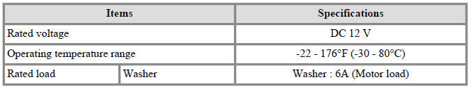
Specifications
Multifunction Switch / Components And Components Location
- Steering column shaft
- Lighting switch
- Wiper/Washer switch
- Screws
- Clock spring
LHD
RHD
Multifunction Switch / Repair Procedures
Removal
- Disconnect the negative (-) battery terminal.
- Remove the steering wheel.
(Refer to Steering System - "Steering Wheel")
- Remove the steering column upper and lower shrouds after loosening the
screws.
(Refer to Body - "Steering Column Shroud Panal")
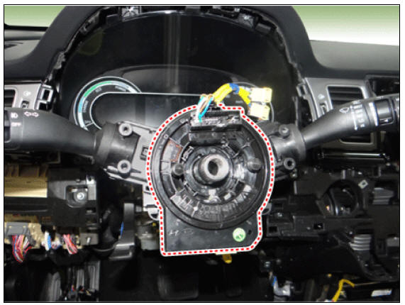
- Remove the clock spring.
(Refer to Restraint - "Driver Airbag (DAB) Module and Clock Spring")
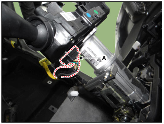
- Disconnect the multifunction switch connector (A).
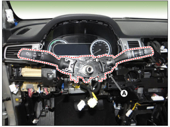
- Remove the multifunction switch assembly (A) after loosening the screws.
Installation
- Install in the reverse order of removal.
Warning
Work with fully understanding of repair procedure and caution relating to clock spring.
(Refer to Restraint - "Driver Airbag (DAB) Module and Clock Spring")
- Check if the steering wheel remote control, airbag system and horn are normally operating after turning the handle all the way left and right when installing air bag module is done.
Inspection
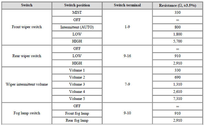
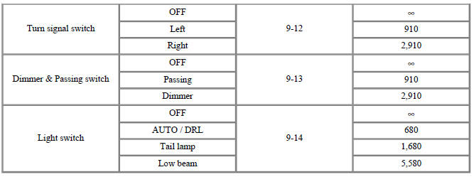
Multifunction Switch Inspection
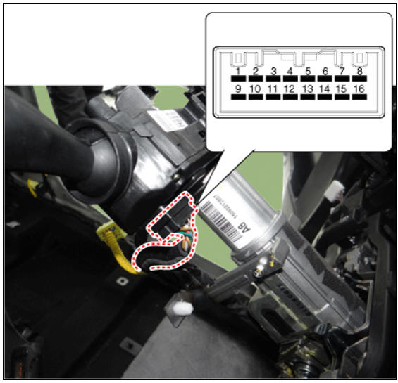
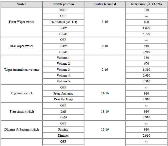
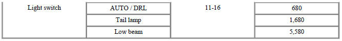
- Check for continuity between the terminals in each switch position as shown below.
Left Handle Drive
Right Handle Drive
Inspection (With KDS)
- In the body electrical system, failure can be quickly diagnosed by using
the vehicle diagnostic system (KDS).
The diagnostic system(KDS) provides the following information.
(1) Self diagnosis : Checking failure and code number (DTC)
(2) Current data : Checking the system input/output data state
(3) Actuation test : Checking the system operation condition
(4) Additional function : Controlling other features including system option setting and zero point adjustment
- Select the 'Car model' and the 'Body Control Module (BCM)' to be checked in order to check the vehicle with the tester.
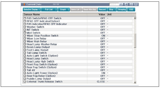
- Select the 'Current Data' menu to search the current state of the input/output data.
READ NEXT:
 Power Door Locks
Power Door Locks / Components And Components Location
Driver power window switch
Assist power window switch
Integrated Gateway & Power control Module (IGPM)
Door lock knob
Tailgate latch assembly
Door latch assembly
Door lock/
Power Door Lock Module Repair procedures
Inspection
Warning
When removing with a flat-tip screwdriver or remover, wrap
protective tape around the tools to
prevent damage to components.
When removing the interior trim pieces, use a plastic panel
removal tool not to damage the
Power Door Lock Switch Repair procedures
Inspection
Non-IMS Type
Check for continuity between the terminals. If there is an abnormality,
replace the switch.
IMS Type
Diagnosis With KDS
The body electrical system can be quickly diagnosed for failed parts by
using v
SEE MORE:
Parking Brake Cable Repair procedures
Removal
Turn ignition switch OFF and disconnect the negative (-) battery
terminal.
Remove the crash pad lower panel.
(Refer to Body - "Crash Pad")
Remove the knee air bag.
(Refer to Restraint - "Knee Airbag(KAB) Module&q
Tailgate Assembly
Tailgate / Repair Procedures
Adjustment
After loosening the tailgate hinge (A) mounting
bolts, adjust the tailgate by moving it up and down, or right and left.
Adjust the tailgate height by turning the tailgate
overslam bumpers (B).
Af
Categories
- Home
- KIA Niro EV, Hybrid - Second generation - (SG2) (2021-2024) - Owner's manual
- Kia Niro - First generation - (DE) (2017-2022) - Service and Repair Manual
- Contact Us