KIA Niro: Clutch Actuator Motor
- Remove the under cover.
(Refer to Engine Mechanical System - "Engine Room Under Cover")
- Remove the front wheel guard (LH).
(Refer to Body - "Front Wheel Guard")
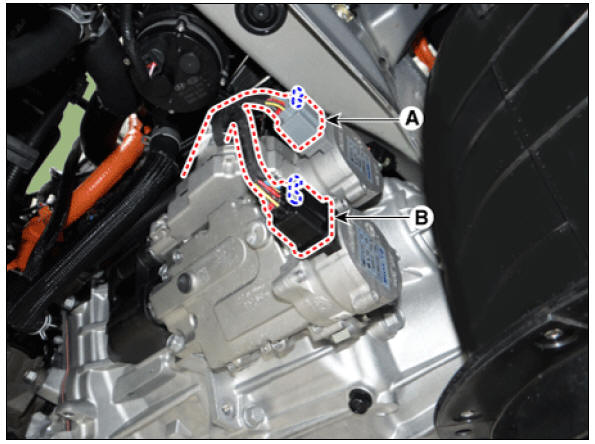
- Disconect the clutch actuator connector (A).
- Motor 1 (Odd)
- Motor 2 (Even)
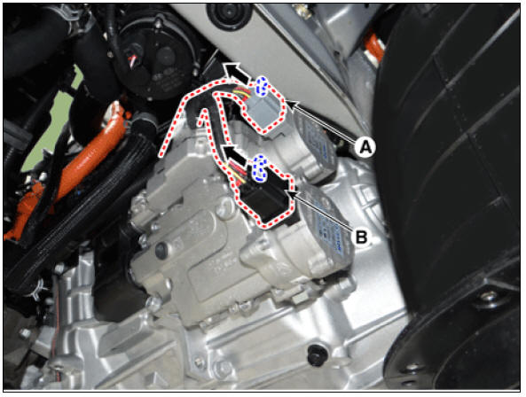
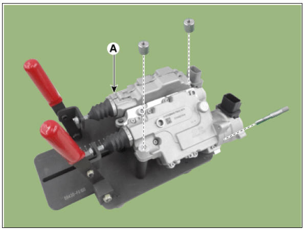
- Remove the clutch actuator motor (A) after loosening the mounting bolts.
- Motor 1 (Odd)
Tightening torque : 3.9 - 5.9 N*m (0.4 - 0.6 kgf*m, 2.9 - 4.3 lb*ft)
- Motor 2 (Even)
Tightening torque : 3.9 - 5.9 N*m (0.4 - 0.6 kgf*m, 2.9 - 4.3 lb*ft)

Installation
Clutch Actuator Assembly
- Install in the reverse order of removal.
Warning
- If clutch actuator needs replacement, measure the pull rod
length of the old clutch actuator to determine if clutch wear
compensation reset is needed.
(Refer to Clutch Actuator Assembly - "Adjustment")
- If needed, perform clutch actuator clutch wear compensation
reset .
(Refer to Clutch Actuator Assembly - "Adjustment")
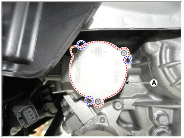
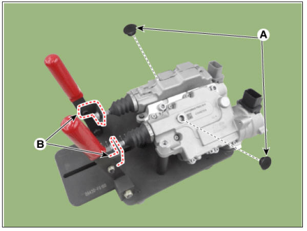
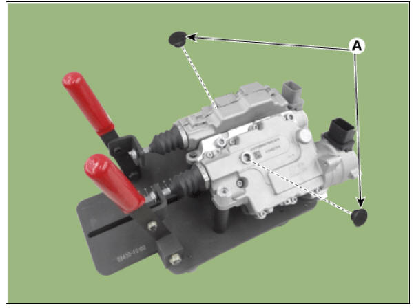
- Check the assembled state of the dowel pins (A) before
installing the clutch actuator assembly.

- When installing, check the color of the motor connectors (A,
B). (A: gray, B: black)

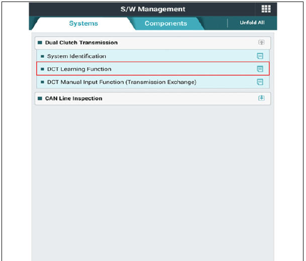
- Perform the clutch touch point learning procedure using the KDS after replacing the clutch actuator assembly.

Clutch Actuator Motor
- Install in the reverse order of removal.
Warning
The existing O-rings (C) and seal bolts (D) must be replaced with a new one while installing the clutch actuator motor. (Do not reuse it)
- Motor 1 (Odd)
- Motor 2 (Even)
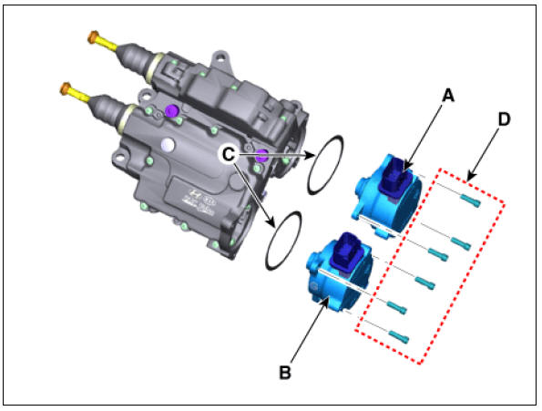
- When installing, check the color of the motor connectors (A,
B). (A: gray, B: black)
Adjustment
Warning
If you replaced the dual clutch assembly or clutch actuator, be sure
to perform wear compensation by referring to the following
table. 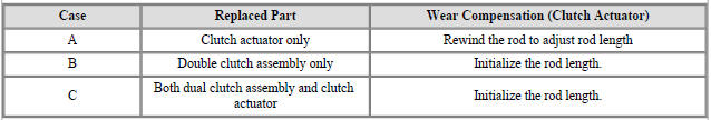
- Rewinding the rod to adjust rod length (when only the clutch actuator is replaced)
Warning
- Be sure to perform it when you have replaced the clutch actuator but reuse the dual clutch assembly.
- It is performed to adjust the rod length of a new clutch actuator to that of an old clutch actuator.
- Remove the clutch actuator assembly.
(Refer to Clutch Actuator Assembly - "Removal")
- Disconnect the clutch actuator motor connector.
1) Remove the clutch actuator motor connector wiring bracket (A).

2) Disconnect the clutch actuator motor connector (B).

Warning
To measure the rod length of an old clutch actuator, perform the steps No. 3 - 4 of the following procedure.
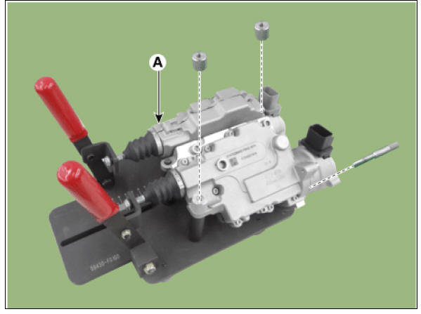
- Install the faulty clutch actuator (A) on special service tool (09430-F0100) and fix the actuator using nuts and bolts.
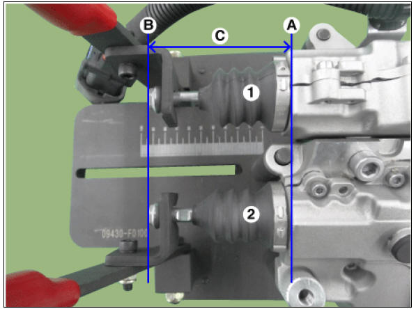
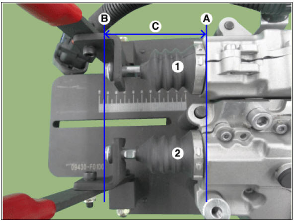
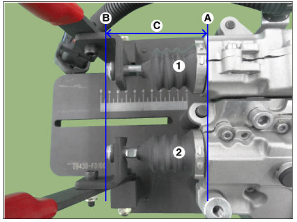
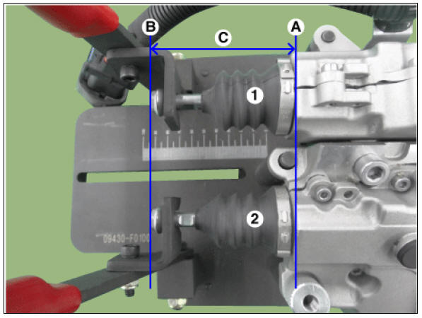
- Slightly pull the lever of the clutch actuator removed from the vehicle and measure the length of each old rod (C).
Length of the old rod (C) : Length from the reference plane (A) to the end of the rod (B).
- Clutch actuator 1
- Clutch actuator 2

Warning
If the rod length is less than 57 mm (2.2441 in.) replace all of the dual clutch assembly, clutch actuator, and engagement bearing.
- Remove the clutch actuator from the special service tool (09430-F0100).
Warning
To match the rod length of a new clutch actuator with that of the clutch actuator removed from the vehicle, perform the steps No. 6 - 15 of the following procedure.
- Install the clutch actuator (A) on special service tool (09430-F0100) and fix the actuator using nuts and bolts.

- Fix the pull rod to hook (B) and then remove sealing rubber (A).

- Slightly pull the lever of the new clutch actuator and measure the length of each new rod (C).
Length of the new rod (C) : Length from the reference plane (A) to the end of the rod (B).
- Clutch actuator 1
- Clutch actuator 2
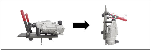
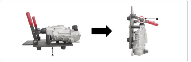
- With the clutch actuator fixing jig (09430-F0100) (A) installed, stand the clutch actuator vertically.
- After standing it vertically, remove the hook (B) from the rod.
- Press the end part of rod (A) and release the pressing force when you see the nut bump (B).

Warning
- Light inside of the hole (C) and check the nut bump (B) inside of it.
- Repeat the operation if the nut bump (B) does not come down to the assembly hole position.
- The nut bump (B) can be moved up a little by sealing boot if the pressing force is released.
- Insert a special tool (09430-C1300) (A) to a sealing rubber hole.
Rotate the SST clockwise and adjust the length of the new clutch actuator's rod to the "length of old rod", which was measured at step No. 4.
Increasing (+) rod length : Rotate counter-clockwise / once +0.25mm
(+0.0009 in.)
Shortening (-) rod length : Rotate clockwise / once -0.25mm (-0.0009 in.)

Warning
Perform the same procedure for the opposite side rod.
Warning
- Be aware not to break the clutch actuator caused by break away inner parts when the SST over rotates clockwise.
- IIf the "length of the clutch actuator's new rod" is not adjusted to the "length of the old rod" measured at step No. 4, the DCT shift shock may occur or driving may be impossible.
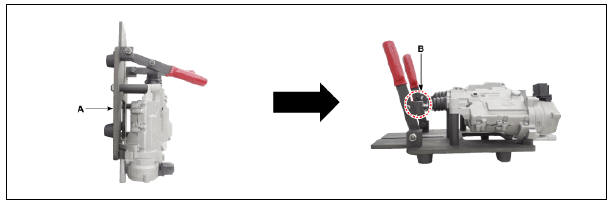
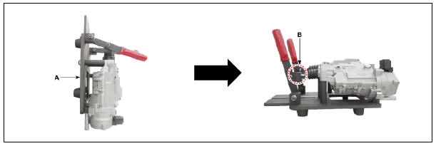
- With the clutch actuator fixing jig (09430-F0100) (A) mounted, maintain the level of the clutch actuator.
- With the fixing jig (09430-F0100) levelled, install the hook (B) on the clutch actuator.
- Slightly pull the lever of the clutch actuator and check whether the "length of the rod which the final adjustment is finished" is same with the "length of the old rod" measured at step No. 4.
Rod length (C) : Length from the reference plane (A) to the end of the rod (B).
- Clutch actuator 1
- Clutch actuator 2
- Install the sealing rubber (A).

- Remove the clutch actuator assembly from the special tool (09430-F0100).
B. Initializing the rod length (When only the dual clutch assembly is replaced or Both dual clutch assembly and clutch actuator is replaced)
Warning
- Be sure to perform it when you have replaced the dual clutch assembly but reuse the clutch actuator.
- Perform the procedure when both the dual clutch assembly and clutch actuator are replaced.
- It is performed to adjust the rod length of an old clutch actuator to that of a new clutch actuator.
- Remove the clutch actuator assembly.
(Refer to Clutch Actuator Assembly - "Removal")
- Install the clutch actuator (A) on special service tool (09430-F0100) and fix the actuator using nuts and bolts.
- Fix the pull rod to hook (B) and then remove sealing rubber (A).
- Slightly pull the lever of the clutch actuator removed from the vehicle and measure length of each rod (C). If the length is shorter than the initialization length, you need to perform initialization.
Rod length (C) : Length from the reference plane (A) to the end of the rod (B).
( Initializ rod length : 82.0 - 83.0 mm (3.2283 - 32677 in.)
- Clutch actuator 1
- Clutch actuator 2
- Stand the clutch actuator vertically with SST (09430-F0100) (A) installed.
- After standing it vertically, remove the hook (B) from the rod.
- Press the end part of rod (A) and release the pressing force when you see the nut bump (B).

Warning
- Light inside of the hole (C) and check the nut bump (B) inside of it.
- Repeat the operation if the nut bump (B) does not come down to the assembly hole position.
- The nut bump (B) can be moved up a little by sealing boot if the pressing force is released.
- Insert a special tool (09430-C1300) (A) to a sealing rubber hole.
Rotate the SST counter-clockwise and adjust the length of the clutch actuator's rod.
Increasing (+) rod length : Rotate counter-clockwise / once +0.25mm (+0.0098 in)
Shortening (-) rod length : Rotate clockwise / once -0.25mm (-0.0098 in)

Warning
Perform the same procedure for the opposite side rod.
Warning
- Be aware not to break the clutch actuator caused by break away inner parts when the SST over rotates clockwise.
- If the rod length is not initialized to 82.0 - 83.0 mm (3.2283 - 32677 in.) ( during initialization of wear compensation, DCT shift shock may occur or driving may be impossible.
- With the clutch actuator fixing jig (09430-F0100) (A) mounted, maintain the level of the clutch actuator.
- With the fixing jig (09430-F0100) levelled, install the hook (B) on the clutch actuator.
- Slightly pull the lever of the clutch actuator and check whether the "length of the rod which the final adjustment is finished" is same with the "rod's initialized length".
Rod length (C) : Length from the reference plane (A) to the end of the rod (B).
( Initializ rod length : 82.0 - 83.0 mm (3.2283 - 32677 in.)
- Clutch actuator 1
- Clutch actuator 2
- Install the sealing rubber (A).
- Remove the clutch actuator assembly from the special tool (09430-F0100).
READ NEXT:
 Gear Actuator Assembly, Repair procedures
Component Location
Gear actuator assembly
Shift motor 2 (Even)
Shift motor 1 (Odd)
Select solenoid 2 (Even)
Select solenoid 1 (Odd)
Specification
Gear Actuator Assembly Description and operation
Description
Input speed sensor | Inhibitor Switch
Component Location
Input speed sensor
Specification
Input Speed Sensor Description and operation
Description
The input shaft speed sensor is important in that it detects the input shaft RPM and sends this information to the
SEE MORE:
Forward Collision-Avoidance Assist settings
Forward safety
A: Driver Assistance
Driving Safety
Forward Safety
With the vehicle on, touch Settings ?
Driver Assistance ? Driving Safety on
the instrument cluster or Settings ?
Vehicle ? Driver Assistance ? Driving
Safety on t
Coolant Repair procedures
Refilling And Bleeding
Warning
Never remove the cap when the engine is hot. Serious scalding could
be caused by hot fluid under high pressure escaping
from the reservoir.
Warning
When pouring inverter coolant, be sure to shut the relay box lid
Categories
- Home
- KIA Niro EV, Hybrid - Second generation - (SG2) (2021-2024) - Owner's manual
- Kia Niro - First generation - (DE) (2017-2022) - Service and Repair Manual
- Contact Us