KIA Niro: Gear Actuator Assembly, Repair procedures
Component Location
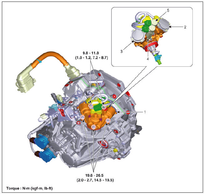
- Gear actuator assembly
- Shift motor 2 (Even)
- Shift motor 1 (Odd)
- Select solenoid 2 (Even)
- Select solenoid 1 (Odd)
Specification

Gear Actuator Assembly Description and operation
Description
- The gear actuator comprises the shift motor and select solenoid.
- Gear actuator shift motor and select solenoid use signals from TCM to control the gear.

Schematic Diagrams

Gear Actuator Assembly Repair procedures
Removal
Warning
- Be sure to read and follow the "General Safety Information and Caution" before doing any work related with the high voltage system. Failure to follow the safety instructions may result in serious electrical injuries.
- Be sure to shut off the high voltage circuit according to the "High Voltage Shut-off Procedures" before doing any work related with the high voltage system to avoid serious electrical injuries.
- Shut off the high voltage circuit.
(Refer to Double Clutch Transmission System - "High Voltage Shut-off Procedure")
- Drain the coolant of hybrid cooling system.
(Refer to Hybrid Motor System - "Coolant")
- Remove the hybrid power control unit (HPCU) assembly.
(Refer to Hybrid Control System - "Hybrid Power Control Unit")
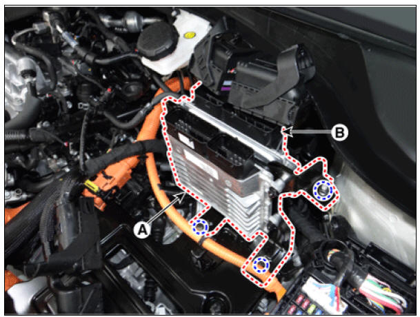
- Disconnect the TCM connector (A) and ECM connector (B).
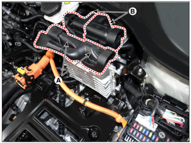
- Remove the TCM (A) and ECM (B).
Tightening torque : 9.8 - 11.8 N*m (1.0 - 1.2 kgf*m, 7.2 - 8.7 lb*ft)
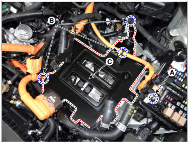
- Remove the HPCU tray (C) after removing the nut (A) and wiring mounting clips (B).
Tightening torque : (A) 10.8 - 13.7 N*m (1.1 - 1.4 kgf*m, 8.0 - 10.1 lb*ft) (C) 21.6 - 23.5 N*m (2.2 - 2.4 kgf*m, 15.9 - 17.4 lb*ft)
- Disconnect the gear actuator motor connector (A) and gear actuator solenoid connector (B).
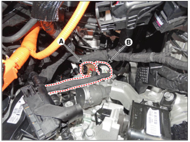
- Remove the gear actuator assembly after loosening bolts (A, B).
Tightening torque :
(A) 19.6 - 26.5 N*m (2.0 - 2.7kgf*m, 14.5 - 19.5 lb*ft)
(B) 9.8 - 11.8 N*m (1.0 - 1.2kgf*m, 7.2 - 8.7 lb*ft)

Installation
- Install in the reverse order of removal.
Warning
Check the following before installing the gear actuator assembly.
1) Check that the gear actuator is placed in the "neutral" state.
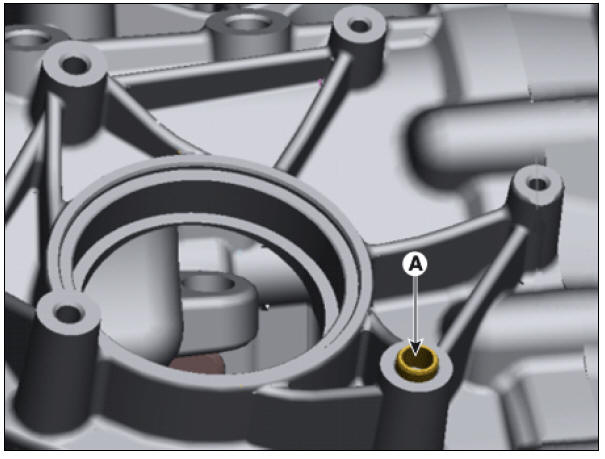
2) Check the assembled state of the O-rings (A). 
3) Apply gear oil to the surface of O-rings.
4) Check the assembled state of the dowel pins (A).
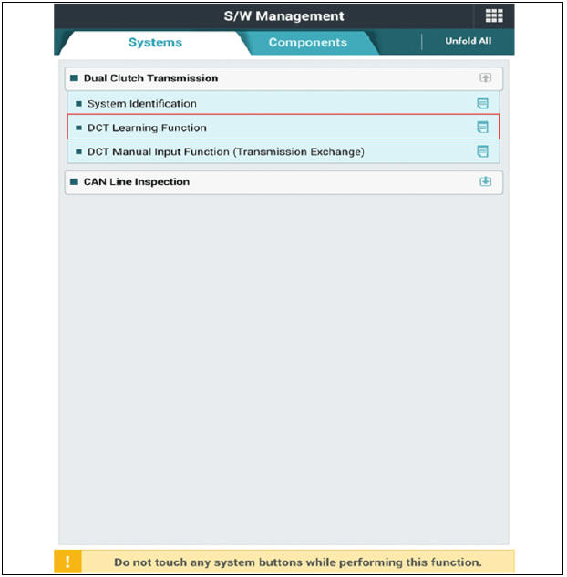
- Perform the clutch touch point learning procedure using the KDS after replacing the gear actuator assembly
READ NEXT:
 Input speed sensor | Inhibitor Switch
Component Location
Input speed sensor
Specification
Input Speed Sensor Description and operation
Description
The input shaft speed sensor is important in that it detects the input shaft RPM and sends this information to the
SEE MORE:
ESP(Electronic Stability Program) System / Description And Operation
ESP(Electronic Stability Program) System / Components And Components
Location
Pressure Source Unit (PSU)
Integrated Brake Actuation Unit (IBAU)
Front wheel speed sensor
Rear wheel speed sensor
Description
Electronic Stability Prog
High Voltage System
Vehicle components
12V auxiliary battery
The 12V auxiliary battery is located in the right side of the luggage room,
and powers all of the vehicle's standard electronics like
radio, air conditioner, etc. Also, it powers the HPCU (Hybrid
Categories
- Home
- KIA Niro EV, Hybrid - Second generation - (SG2) (2021-2024) - Owner's manual
- Kia Niro - First generation - (DE) (2017-2022) - Service and Repair Manual
- Contact Us