KIA Niro: Input speed sensor | Inhibitor Switch
Kia Niro - First generation - (DE) (2017-2022) - Service and Repair Manual / DCT(Dual Clutch Transmission) System / Dual Clutch Transmission Control System / Input speed sensor | Inhibitor Switch
Component Location
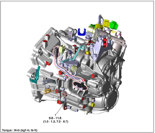
- Input speed sensor
Specification

Input Speed Sensor Description and operation
Description
- The input shaft speed sensor is important in that it detects the input shaft RPM and sends this information to the Transmission Control Module (TCM).
- This data is necessary for all operations including feedback control, gear shift control and failure detection of other sensors.

Schematic Diagrams

Input Speed Sensor Repair procedures
Removal
- Remove the clutch actuator.
(Refer to Double Clutch Transmission Control System - "Clutch Actuator Assembly")
- Remove the connector from the bracket after disconnecting the connector and then remove the input speed sensor (A).
Tightening torque : 9.8 - 11.8 N*m (1.0 - 1.2 kgf*m, 7.2 - 8.7 lb*ft)

Installation
- Install in the reverse order of removal.
Warning
Before installing the input speed sensor, check the assembled state of the O-rings (A) and apply gear oil to the surface of O-rings. 
Inhibitor Switch
Component
Location
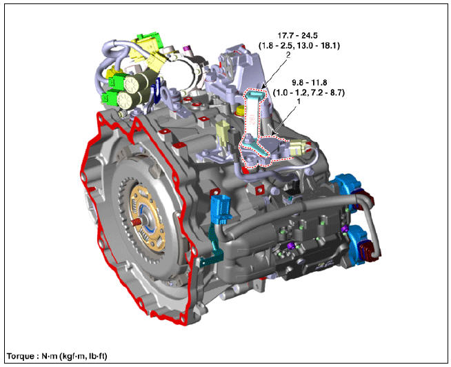
- Inhibitor switch
- Manual control lever
Specification

Signal Code Table

Inhibitor Switch Description and operation
Description
- The inhibitor switch is installed on top of transmission, and is connected to the shift lever through shift cable.
- Inhibitor switch signals (S1, S2, S3, S4) are transmitted to the TCM according to the driver's shift lever control.

Schematic Diagrams

Troubleshooting

READ NEXT:
 Inhibitor Switch Repair procedures
Inspection
Warning
Inspect the following items by referring to inspection flow chart.
(Refer to Inhibitor Switch - "Troubleshooting")
Check the diagnostic trouble codes (DTC) using KDS.
Inspect if "N" range setting matc
Shift Lever | Shift Cable
Components
Shift lever knob & boots
Shift lever assembly
Shift cable assembly
Shift Lever Repair procedures
Removal
Shift the gear to "N".
Remove the knob (A) by pulling it in the direction of arrow af
SEE MORE:
Fuses
Blade type
Cartridge type
Multi fuse
BFT
* Left: Normal, Right: Blown
* The actual fuse/relay panel label may
differ.
Before replacing a blown fuse, disconnect
the negative battery cable.
If the electrical system does not work,
Displaying operating status
You can see the status of the Smart
Cruise Control operation in the Driving
Assist view on the cluster. Refer to "LCD
display modes"
Smart Cruise Control will be displayed as
below depending on the status of the
function.
Operating
Categories
- Home
- KIA Niro EV, Hybrid - Second generation - (SG2) (2021-2024) - Owner's manual
- Kia Niro - First generation - (DE) (2017-2022) - Service and Repair Manual
- Contact Us