KIA Niro: Integrated Memory System (IMS) / Description And Operation
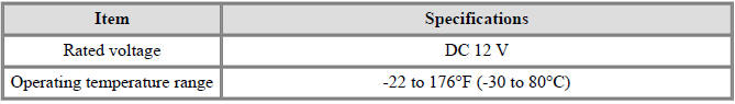
Specifications
Memory Power Seat Unit

Memory Power Seat Switch
Integrated Memory System (IMS) / Components And Components Location
- Memory power seat unit (PSM)
- IMS control switch
- Outside rear view mirror
- IMS mirror control (Driver Door Module (DDM))
Integrated Memory System (IMS) / Schematic Diagrams
Integrated Memory System (IMS) / Description And Operation
Description
The optimum seat position set by the driver is memorized in the power seat unit by IMS switch control to be recalled by using the IMS switch even if the seat position has been changed.
It is equipped with safety functions such as prohibition of recalling and emergency stopping of linked motion while driving.
Manual Operation
The position of the seat is changed by operating the motor when the signal is input with manual switch for the seat (Slide, recline, front tilt, rear height adjusting)
Memory function
Can memorize and recall data for up to two persons with IMS switch.
- Memorized operations of seat and outside rearview mirror positions are operated by IMS switch via CAN (IMS → DDM) when the optimum seat position is set by the driver.
- Recall by the CAN data received from IMS switch control.
Linked motion for getting on/off
- The driver's seat moves backward when the driver get off from the vehicle.
- Condition for operating getting on : When the electric power is in ACC, When Engine OFF, if the driver close the driver side door with carring samrt key (When ON at the User Setting Mode)
- Condition for operating getting off : When the electric power off and open the driver door.
Operation
Recall operation
- The buzzer will operate once and automatically be adjusted to the memorized position when the CAN data from IMS is received.
- Unsaved recall signals will not be performed.
- If another recall signal is received during recall operation, the last received recall signal prevails.
- If recall signal is received by pressing switch 1 or 2 during recall operation, the seat will stop recall operation.
- If memory signal is received by pressing SET button during recall operation, the seat will stop the recall operation.
Warning
Press the SET button once more to store the position of stop.
- Automatically stop at the virtual limit position during recall operation.
- If the difference between memorized position and current position is less than 4 pulses, motor will not be operated.
Conditions for prohibiting recall operation
Recall operation is prohibited and recall operation is stopped if any of the following conditions is met.
- IGN2 OFF (except within 30 seconds of opening or closing door)
- Over 3 km/h of vehicle speed
- In case of manual switch manipulation
- Operation time chart
Decision on the operation priority
- The motor operation shall be delayed for 100+-10 milliseconds to prevent
the overlapping of inrush
circuit during motor start. In this case, the priority is as follows.
Slide > Backrest adjustment >Front height adjustment >Rear height adjustment Operation time chart
Operation linked with getting on/getting off
- Return operations backwards when getting off and forward when getting on (slide type only)
- It is available when the automatic SET message transmitted from the driver seat power window switch (DDM) is ON.
Warning
Applied only to driver's settings menu (USM) is on.
- Starting of operation when the electric power off and open the driver door.
- Move to the target potision of ACC ON.
- Condition for prohibiting operation
- Over 1.8 MPH (3km/h) of vehicle speed
- In case of power seat manual control switch manipulation
- On receiving recall command during operation for getting on
- Driver Settings Manu (USM) is Off
READ NEXT:
 Memory Power Seat Unit
Memory power seat unit Components and components location
Connector Pin Information
Memory power seat unit Repair procedures
Removal
Before removing the driver side seat assembly, pull it upward to the
maximum by pushing the fro
Memory Power Seat Switch
Connector and Terminal Function
Memory power seat switch Repair procedures
Removal
Disconnect the negative (-) battery terminal.
Remove the driver front door trim.
(Refer to Body - "Front Door Trim")
Remove the memory power
SEE MORE:
Intake Actuator
Intake Actuator Components and components location
Intake actuator
Description
Located in the blower unit, the intake actuator regulates the intake door
based on the signal from the
control unit. Pressing the intake selection switch wi
Fuel Pressure Regulator Repair procedures | Fuel Line Repair procedures
Removal
Remove the fuel pump.
(Refer to Fuel Delivery System - "Fuel Pump")
Disconnect the fuel pump motor connector (A) and fuel sender connector (B).
Lift the fixing hook (A) by using a comm
Categories
- Home
- KIA Niro EV, Hybrid - Second generation - (SG2) (2021-2024) - Owner's manual
- Kia Niro - First generation - (DE) (2017-2022) - Service and Repair Manual
- Contact Us