KIA Niro: Memory Power Seat Unit
Memory power seat unit Components and components location
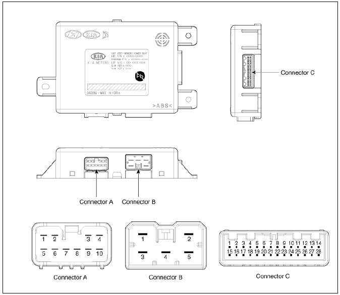
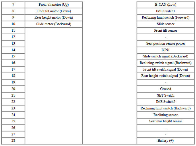
Connector Pin Information

Memory power seat unit Repair procedures
Removal
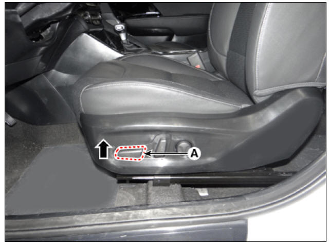
- Before removing the driver side seat assembly, pull it upward to the maximum by pushing the front seat height adjusting switch (A).
- Disconnect the negative (-) battery terminal
- Remove the driver front seat assembly.
(Refer to Body - "Front Seat Assembly")
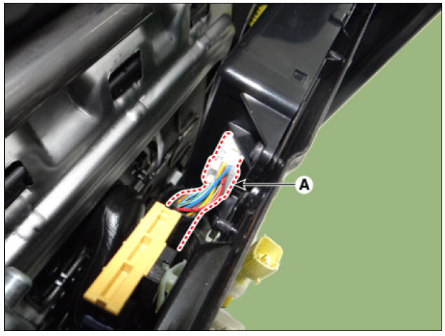
- Disconnect the IMS unit connectors (A).
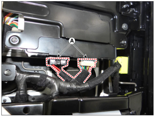
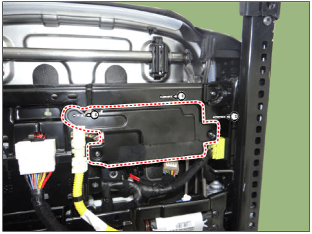
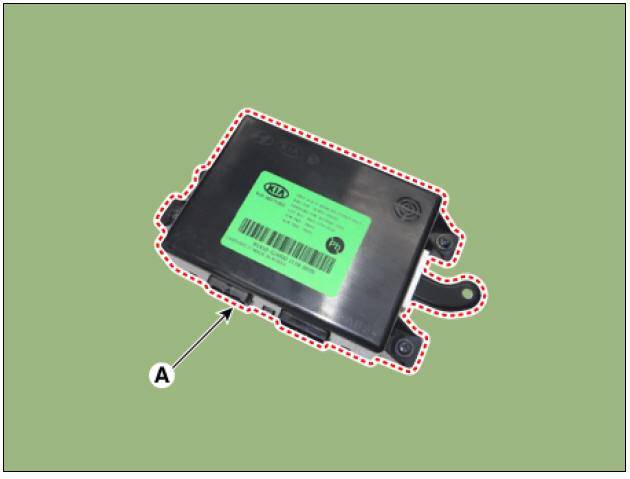
- Remove the IMS unit (A) after loosening the mounting screws.
Installation
- Install in the reverse order of removal.
Inspection
Diagnosis with KDS
- In the body electrical system, failure can be quickly diagnosed by using the vehicle diagnostic system (KDS).
The diagnostic system (KDS) provides the following information.
(1) Self diagnosis : Checking failure and code number (DTC)
(2) Current data : Checking the system input/output data state
(3) Actuation test : Checking the system operation condition
(4) Additional function : Controlling other features including system option setting and zero point adjustment
- Select the 'Car model' and the 'Memory Power Seat Module (DPSM/APSM)' to be checked in order to check the vehicle with the tester.
- Select the 'Current Data' menu to search the current state of the input/output data.
READ NEXT:
 Memory Power Seat Switch
Connector and Terminal Function
Memory power seat switch Repair procedures
Removal
Disconnect the negative (-) battery terminal.
Remove the driver front door trim.
(Refer to Body - "Front Door Trim")
Remove the memory power
 Keyless Entry And Burglar Alarm / Description And Operation
Keyless Entry And Burglar Alarm / Components And Components Location
Specification
Hood switch
Horn (High-pitch)
Horn (Low-pitch)
Body control module (BCM)
Door lock/unlock buzzer
Front door actuator & switch
Rear door ac
SEE MORE:
 Piston, rings
Clean piston.
(1) Using a gasket scraper, remove the carbon from the piston top.
(2) Using a groove cleaning tool or broken ring, clean the piston ring grooves.
(3) Using solvent and a brush, thoroughly clean the piston.
Warning
Do not
 Front Brake
Inspection
Check the pads for excessive wear, discs for run out and wear, and calipers
for fluid leakage.
Front brake disc thickness check
Check the brake pads for wear and fade.
Check the brake disc for damage and cracks.
Remove all rust
Categories
- Home
- KIA Niro EV, Hybrid - Second generation - (SG2) (2021-2024) - Owner's manual
- Kia Niro - First generation - (DE) (2017-2022) - Service and Repair Manual
- Contact Us
