KIA Niro: Front / Rear Outlet Cooling Duct
Kia Niro - First generation - (DE) (2017-2022) - Service and Repair Manual / Hybrid Control System / High Voltage Battery Cooling System / Front / Rear Outlet Cooling Duct
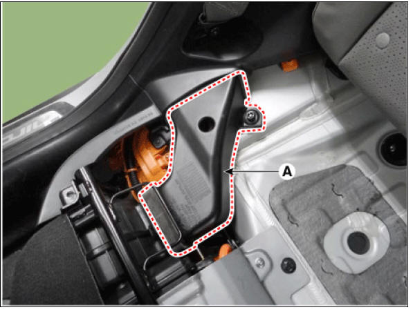
Front Outlet Cooling Duct
- Switch "OFF" the ignition and disconnect the negative (-) terminal of the auxiliary 12V battery.
- Shut off the high voltage circuit.
(Refer to Hybrid Control System - "High Voltage Shutoff Procedure")
- Remove the rear seat cushion.
(Refer to Body - "Rear Seat Assembly")
- Remove the front outlet duct (A).

Rear Outlet Cooling Duct
- Switch "OFF" the ignition and disconnect the negative (-) terminal of the auxiliary 12V battery.
- Shut off the high voltage circuit.
(Refer to Hybrid Control System - "High Voltage Shutoff Procedure")
- Remove the high voltage rear cover (A) after loosening the mounting bolt.
High Voltage Battery Rear Cover mounting bolt : 7.8 - 11.8 N*m (0.8 - 1.2 kgf*m, 5.8 - 8.7 lb*ft)
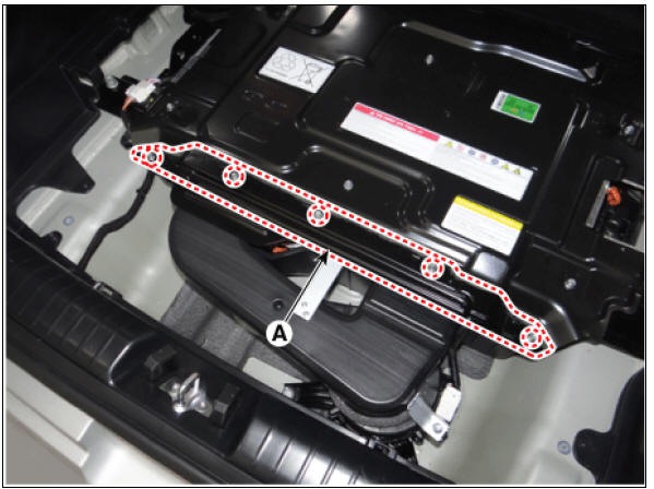
- Remove the rear outlet cooling duct (A) after loosening the mounting bolt.
Rear Outlet Cooling Duct mounting bolt : 7.8 - 11.8 N*m (0.8 - 1.2 kgf*m, 5.8 - 8.7 lb*ft)

Installation
Warning
- Be sure to read and follow the "General Safety Information and Caution" before doing any work related with the high voltage system. Failure to follow the safety instructions may result in serious electrical injuries.
- Be sure to read and follow the "High Voltage Shut-off Procedures" before doing any work related with the high voltage system. Failure to follow the safety instructions may result in serious electrical injuries.
- Install the cooling ducts in the reverse order of removal.
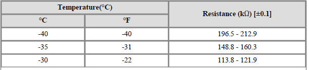
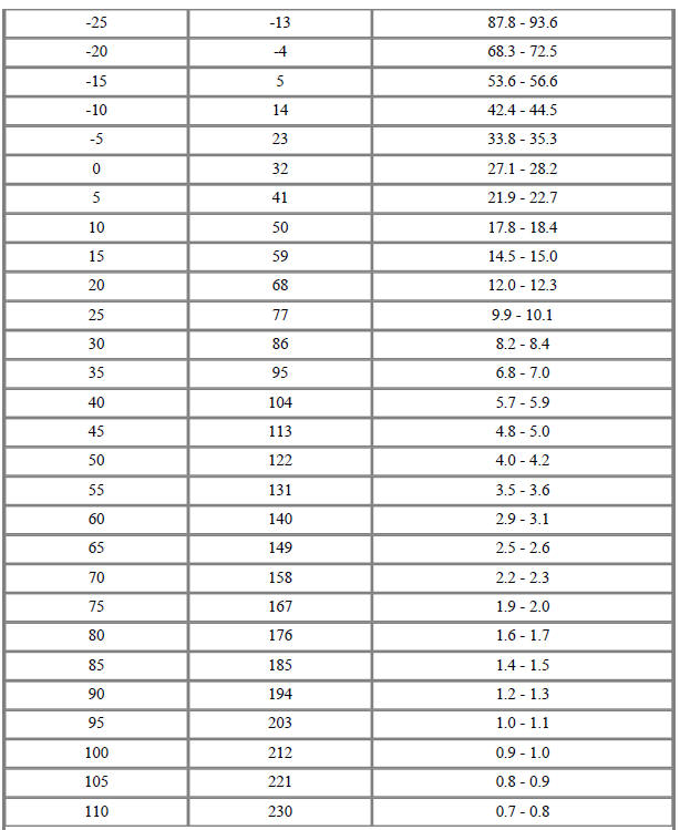
Air Inlet Temperature Sensor
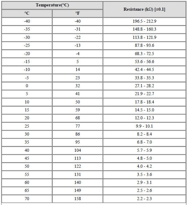
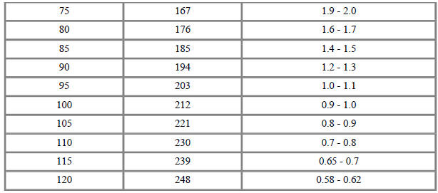

Battery Temperature Sensor (Side of cell)


READ NEXT:
 Inlet Temperature Sensor
Inlet Temperature Sensor #1 (Main High Voltage)
Description
The inlet temperature sensor is installed on top of the high voltage battery
module, and it detects the
air temperature inside the battery system assembly.
The inlet temperatur
Low Voltage DC/DC Converter
Specification
Description
The Low Voltage DC/DC is integrated into the HPCU. It charges the auxiliary
battery as a substitute
for generator by converting the high voltage (DC 270V) from the high voltage
battery into low voltage
(DC 12V).
Power Cable
Components
Power Cable (HPCU↔Main High Voltage Battery
System)
Power Cable (HPCU↔HSG, Electric /C Compressor)
Power Cable (Main High Voltage Battery System ↔ Sub
High Voltage Battery System)
Removal
Warning
Be sure to re
SEE MORE:
Resolver Sensor | Motor Temperature Sensor
Description
The accurate position of the rotor must be known at all times to ensure maximum output control of the motor.
Part Circuit Diagram
Hybrid Drive Motor
HSG
Resolver Sensor Repair procedures
Inspection
Hybrid Drive Motor
Relay Box (Passenger Compartment)
IGPM
Description
Communication Network Diagram
Integrated Gateway & Power control Module (IGPM)
Integrated Gateway & Power control Module (IGPM) is a module that performs
the function of conventional Junction Block and
Categories
- Home
- KIA Niro EV, Hybrid - Second generation - (SG2) (2021-2024) - Owner's manual
- Kia Niro - First generation - (DE) (2017-2022) - Service and Repair Manual
- Contact Us