KIA Niro: Electrical Circuit Inspection Procedure
Open Circuit Test
- Procedures for Open Circuit
- Continuity Check
- Voltage Check
If an open circuit occurs (as seen in (FIG. 1)), it can be found by performing Step 2 (Continuity Check Method) or Step 3 (Voltage Check Method) as shown below.
- Continuity Check Method
Warning
When measuring the resistance, lightly shake the wire harness vertically or horizontally.
Specification (Resistance)
1Ω or less → Normal Circuit
1MΩ or Higher → Open Circuit
- Disconnect connectors (A) and (C), and measure resistance between
connectors (A) and (C) as shown in (FIG. 2).
In (FIG. 2), if the measured resistances in lines 1 and 2 are "over 1 MΩ" and "below 1 Ω" respectively, line 1 has an open circuit. (Line 2 is normal.) To find the exact broken point, check the sub line of line 1 as described in the next step.
- Disconnect connector (B), and measure the resistances between connectors
(C) and (B1), and between (B2) and (A) as
shown in (FIG. 3).
In this case, the measured resistance between connectors (C) and (B1) is higher than 1 MΩ and the open circuit is between terminal 1 of connector (C) and terminal 1 of connector (B1).
- Voltage Check Method
- With each connector still connected, measure the voltage between the
chassis ground and terminal 1 of each of
connectors (A), (B) and (C) as shown in (FIG. 4).
The measured voltages of connectors are 5V, 5V and 0V respectively. So the open circuit is between connectors (C) and (B).
- Short Circuit Test
- Test Method for Short to Ground Circuit
- Continuity Check with Chassis Ground
If short to ground circuit occurs as shown in (FIG. 5), the broken point can be found by performing Step 2 (Continuity Check Method with Chassis Ground) as shown below.
- Continuity Check Method (with Chassis Ground)
Warning
Lightly shake the wire harness vertically or horizontally when measuring the resistance.
Specification (Resistance)
1Ω or less → Short to Ground Circuit
1MΩ or Higher → Normal Circuit
- Disconnect connectors (A) and (C), and measure the resistance between
connector (A) and Chassis Ground as shown in
(FIG. 6).
If the measured resistances in lines 1 and 2 are "below 1 Ω" and "over 1 MΩ" respectively, line 1 has an open circuit.
(Line 2 is normal.) To find the exact broken point, check the sub line of line 1 as described in the next step.
- Disconnect connector (B), and measure the resistances between connector
(A) and chassis ground, and between (B1)
and chassis ground as shown in (FIG. 7).
The measured resistance between connector (B1) and chassis ground is 1Ω or less. The short to ground circuit is between terminal 1 of connector (C) and terminal 1 of connector (B1).
- Voltage Drop Test
- Connect the positive lead of a voltmeter to the end of the wire (or to the side of the connector or switch) closest to the battery.
- Connect the negative lead to the other end of the wire (or the other side of the connector or switch).
- Operate the circuit.
- The voltmeter will show the difference in voltage between the two points. A difference, or drop of more than 0.1 volts (50mV in 5V circuits), may indicate a problem. Check the circuit for loose or dirty connections.

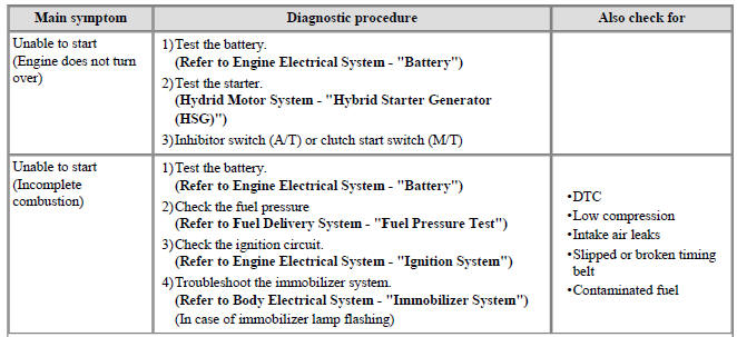
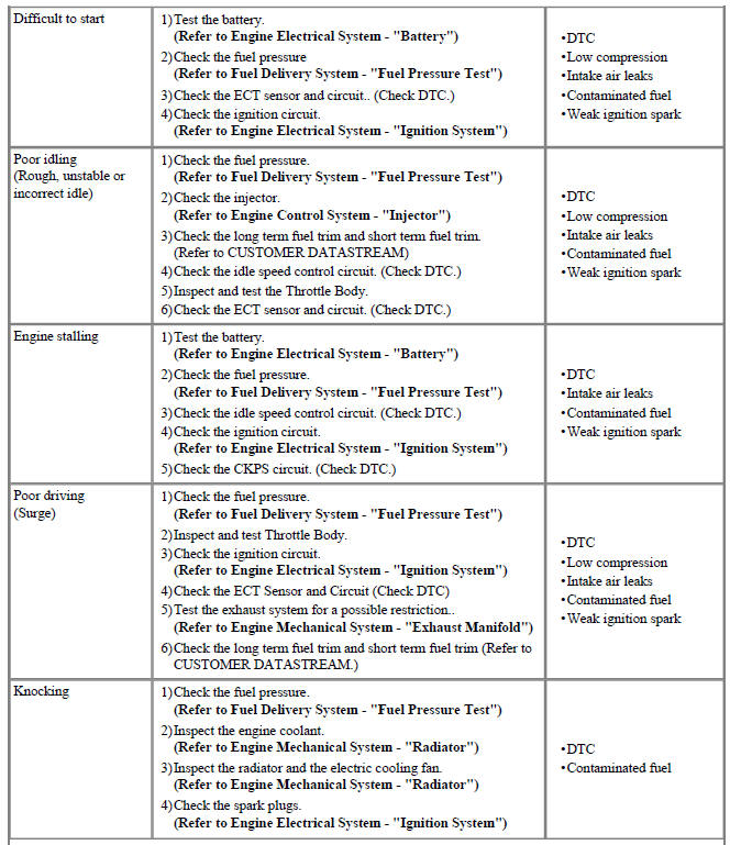
Symptom Troubleshooting Guide Chart

READ NEXT:
 Engine Control System
Components
Location
Engine Control Module (ECM)
Manifold Absolute Pressure Sensor (MAPS)
Mass Air Flow Sensor (MAFS)
Intake Air Temperature Sensor (IATS)
Engine Coolant Temperature Sensor (ECTS) (Water Temperature Control
Assem
Engine Control System / Description And Operation
Description
If the Gasoline Engine Control system components (sensors, ECM, injector, etc.)
fail, interruption to the fuel supply or failure
to supply the proper amount of fuel for various engine operating conditions will
result. The following
Engine Control Module (ECM) Repair procedures
ECM Terminal And Input/Output signal
ECM Terminal Function
Connector (A)
Connector (K)
ECM Terminal Input/Output Signal
Connector (A)
Connector (K)
Engine Control Module (ECM)
SEE MORE:
Vehicle Information Systems (UVO)
AVN head unit
Crash pad LTE antenna (Wi-Fi, LTE 2)
UVO Keypad
Roof LTE antenna (AM/FM + DMB + GPS + LTE 1)
Description
Vehicle information systems (UVO) based on state-of-the-art IT systems,
safety and security
Warning
The term &
Trailer towing
If you are considering towing with your
vehicle, you should first check with your
country's Department of Motor Vehicles
to determine their legal requirements.
Since laws vary the requirements for
towing trailers, cars, or other types of
Categories
- Home
- KIA Niro EV, Hybrid - Second generation - (SG2) (2021-2024) - Owner's manual
- Kia Niro - First generation - (DE) (2017-2022) - Service and Repair Manual
- Contact Us