KIA Niro: Engine Control Module (ECM) Repair procedures
ECM Terminal And Input/Output signal

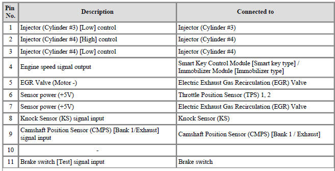
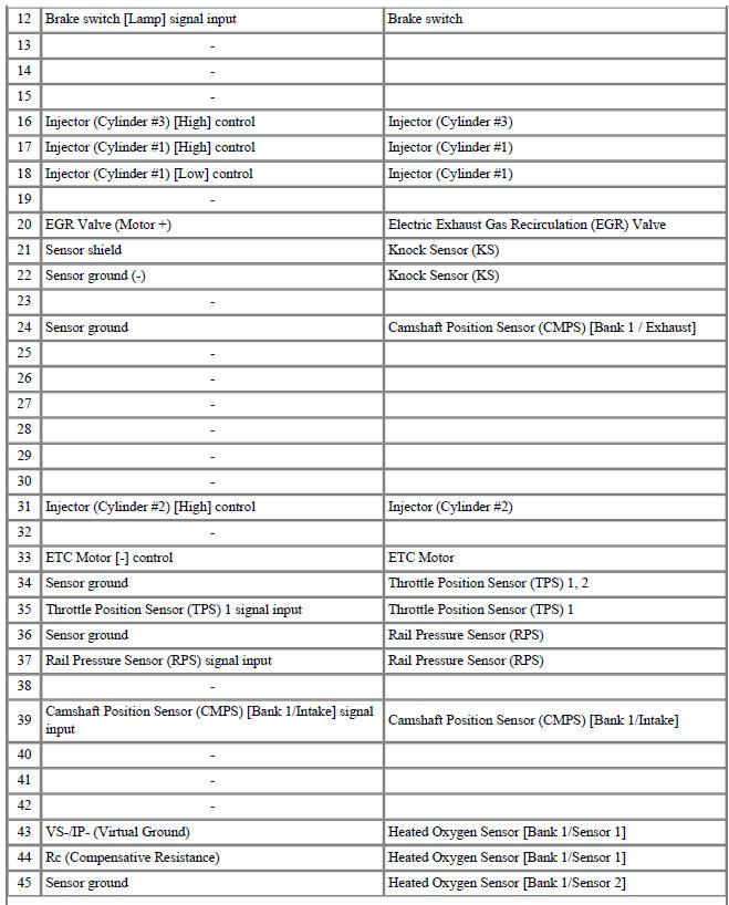
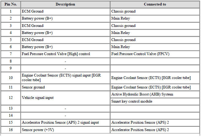
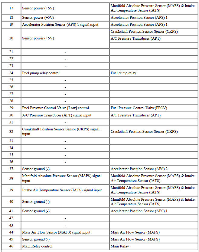
ECM Terminal Function
Connector (A)

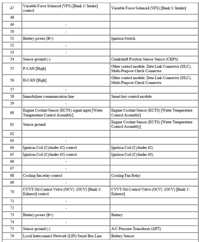
Connector (K)

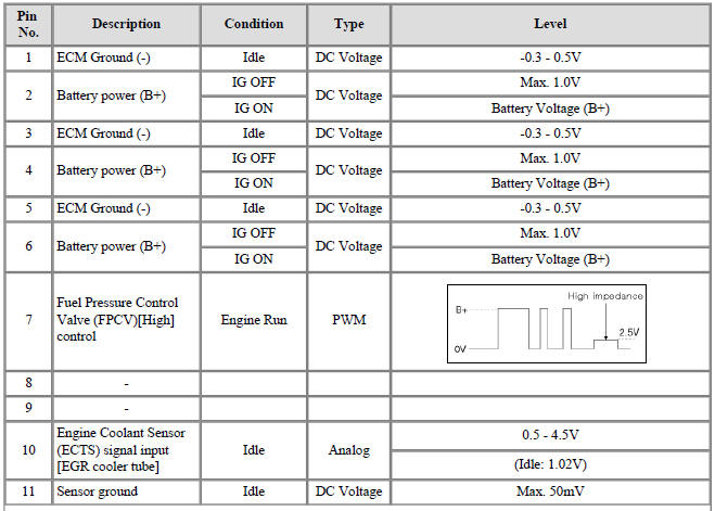
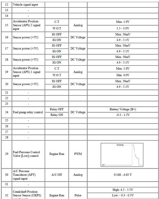
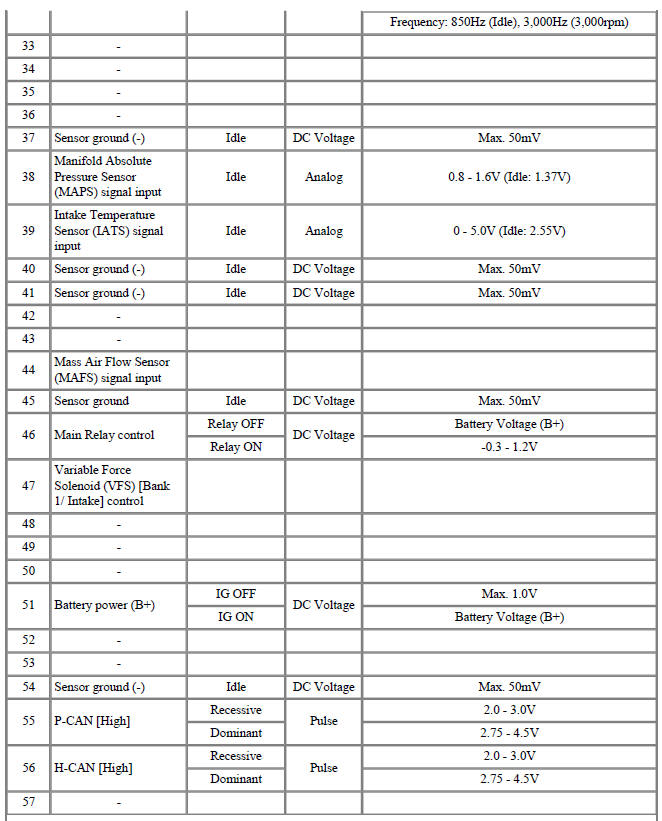
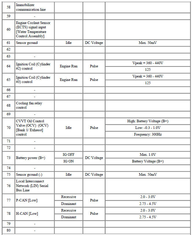
ECM Terminal Input/Output Signal
Connector (A)
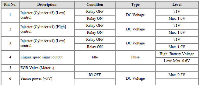
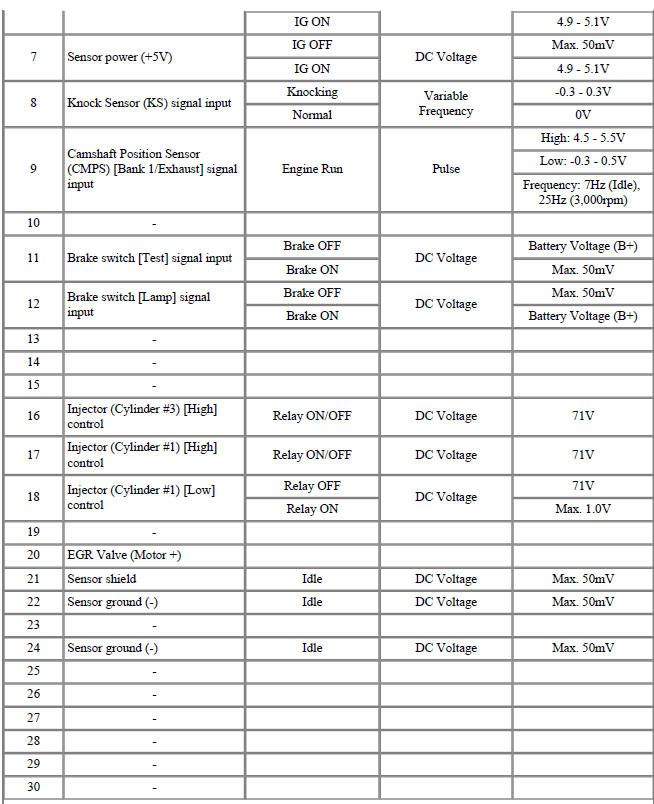
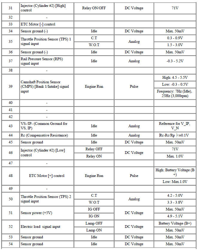

Connector (K)

Engine Control Module (ECM) Repair procedures
Removal
- Switch "OFF" the ignition and disconnect the negative (-) battery terminal.
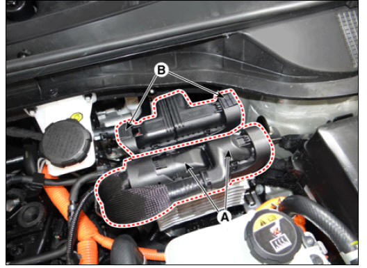
- Disconnect the TCM connectors (A).
- Disconnect the ECM connectors (B).
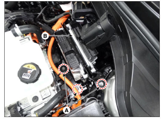
- Remove the ECM & TCM bracket (B) after loosening the mounting nuts (A).
ECM & TCM bracket mounting nut : 9.8 - 11.8 N*m (1.0 - 1.2 kgf*m,7.2 - 8.7 lb*ft)
- Remove the ECM (B) after loosening the mounting nuts (A) from the ECM & TCM bracket.

Installation
- Install in the reverse order of removal.
ECM Problem Inspection Procedure
- TEST ECM GROUND CIRCUIT: Measure resistance between ECM and chassis ground using the backside of ECM harness connector as ECM side check point. If the problem is found, repair it.
Specification: Below 1Ω
- TEST ECM CONNECTOR: Disconnect the ECM connector and visually check the ground terminals on ECM side and harness side for bent pins or poor contact pressure. If the problem is found, repair it.
- If problem is not found in steps 1 and 2, the ECM could be faulty. In this case, make sure that there are no DTC's before replacing the ECM with a new one, and then check the vehicle again. If DTC's are found, examine them first before replacing the ECM.
- RE-TEST THE ORIGINAL ECM: Install the original ECM (possibly broken) into a known-good vehicle and check the vehicle. If the problem reoccurs, replace the original ECM with a new one. If problem does not reoccur, this is an intermittent problem. (Refer to "Intermittent Problem Inspection Procedure" in Basic Inspection Procedure.)
Adjustment
ECM Neutral Mode procedure (With Immobilizer)
- After replacing the ECM of the vehicle with the immobilizer, the
following procedure must be performed.
(If installing a used ECM)
1) Perform "ECM Neutral Mode" procedure using KDS.
(Refer to "Body Electrical System - "Immobilizer System - Repair procedures")
2) After finishing "ECM Neutral Mode", perform "Key Teaching" procedure using KDS.
(Refer to "Body Electrical System - "Immobilizer System - Repair procedures")
If installing a new ECM
Perform "Key Teaching" procedure using KDS.
(Refer to "Body Electrical System - "Immobilizer System - Repair procedures")
ECM Neutral Mode procedure (With Smart key)
- After replacing the ECM of the vehicle with the smart key system (button
start), the following procedure must be performed.
(If installing a used ECM)
1) Perform "ECM Neutral Mode" procedure using KDS.
(Refer to "Body Electrical System - "Smart Key Diagnostic - Repair procedures") 2) After finishing "ECM Neutral Mode", turn IGN ON then OFF using the smart key or start button. Then the ECM learns information on the smart key automatically.
(Refer to "Body Electrical System - "Smart Key Diagnostic - Repair procedures")
(If installing a new ECM) Turn IGN ON then OFF using the smart key or start button. Then the ECM learns information on the smart key automatically.
(Refer to "Body Electrical System - "Smart Key Diagnostic - Repair procedures")
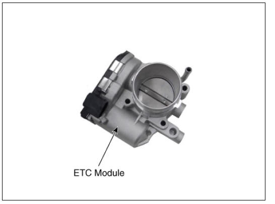
ETC module learning procedure
Perform ETC module learning after replacing the ETC module.
(Refer to Electronic Throttle Control System - "Adjustment")
VIN programming procedure
VIN (Vehicle Identification Number) is a number with the vehicle's information (Maker, Vehicle Type, Vehicle Line/Series, Body Type, Engine Type, Transmission Type, Model Year, Plant Location and so forth. For more information, please refer to "GI" group in this SERVICE MANUAL.). When replacing an ECM, the VIN must be programmed in the ECM. If there is no VIN in ECM memory, the fault code (DTC P0630) is set.
Warning
Carefully check the VIN as it cannot be changed once programmed.
- Select "VIN Writing" function in "Vehicle S/W Management".
- Select "Write VIN" in "ID Register" menu.
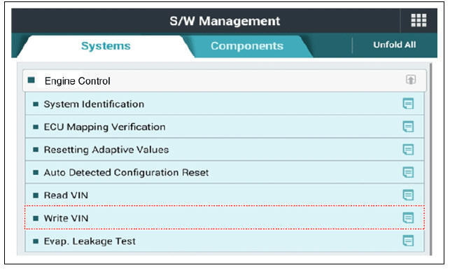
- Enter the VIN.
Warning
Before entering the VIN, confirm the VIN again as it cannot be changed once programmed.

Specification
Throttle Position Sensor (TPS)

ETC Motor

ETC (Electronic Throttle Control) System Description and operation
Description
The Electronic Throttle Control (ETC) System consists of a throttle body with an integrated control motor and throttle position sensor (TPS). Unlike the existing mechanical throttle system that controls the throttle valve by using wire cable connected to the accelerator pedal, the ETC system controls the opening and closing of the throttle valve by the ECM with ETC motor according to the APS (Accelerator Position Sensor) signal mounted to electronic accelerator pedal module. The TPS signal is used to provide feedback regarding throttle position to the ECM. Also, the ETC system has the benefit of implementing cruise control function without additional external cruise control modules/cables.
- Dry bearing
- DC motor
- Non-contact hall sensor
- Gear
- Magnet
- Hall IC
- Yoke
- Stator
Schematic Diagram

Circuit Diagram

Harness Connector

READ NEXT:
 ETC (Electronic Throttle Control) System Repair
Inspection
Connect the KDS on the Data Link Connector (DLC).
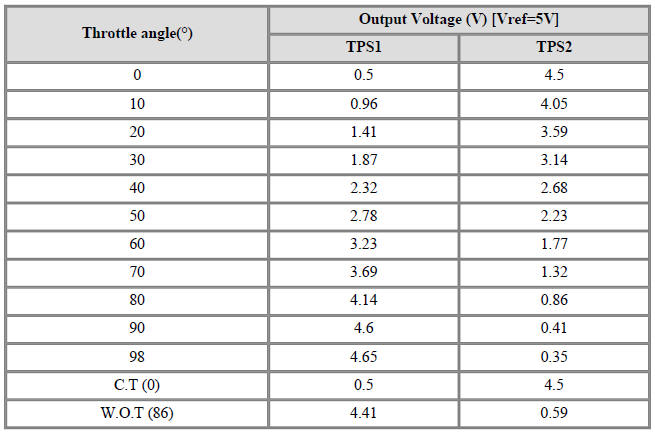
Start the engine and measure the output voltage of TPS 1 and 2 at C.T.
and W.O.T.
Throttle Position Sensor (TPS)
ETC Motor
Switch "OFF" the ignition.
Discon
Manifold Absolute Pressure Sensor (MAPS)
Description
Manifold Absolute Pressure Sensor (MAPS) is a speed-density type sensor
installed on the surge tank.
It senses absolute pressure of the surge tank and transfers the analog signal
proportional to the pressure
to the ECM. By using
Mass Air Flow Sensor (MAFS)
Description
MAFS uses a sensing element made of a hot-film to measure the mass of intake
air entering the engine
and to send the signal to the ECM.
A large amount of intake air represents acceleration or high load conditions
while a small am
SEE MORE:
Wireless smart phone charging system
Indicator
Charging pad
Operation
Place the smartphone at the center of
the wireless charging pad.
The indicator light will change to
orange once the wireless charging
begins. The light will change to green
when charging is c
AC Inverter System / Description And Operation
Specification
AC Inverter System / Components And Components Location
Battery
AC inverter outlet switch
AC inverter unit
AC Inverter System / Description And Operation
Description
An inverter is a device that transforms th
Categories
- Home
- KIA Niro EV, Hybrid - Second generation - (SG2) (2021-2024) - Owner's manual
- Kia Niro - First generation - (DE) (2017-2022) - Service and Repair Manual
- Contact Us