KIA Niro: ETC (Electronic Throttle Control) System Repair
Inspection
- Connect the KDS on the Data Link Connector (DLC).
- Start the engine and measure the output voltage of TPS 1 and 2 at C.T. and W.O.T.
Throttle Position Sensor (TPS)

ETC Motor
- Switch "OFF" the ignition.
- Disconnect the ETC module connector.
- Measure resistance between the ETC module terminals 1 and 2.
- Check that the resistance is within the specification.
Specification: 0.3 - 100 Ω (20ºC (68 ºF))
Removal
- Switch "OFF" the ignition and disconnect the negative (-) battery terminal.
- Remove the air cleaner.
(Refer to Engine Mechanical System - "Air Cleaner")
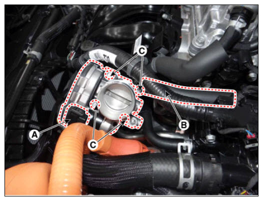
- Disconnect the ETC module connector (A).
- Disconnect the coolant hose (B).
- Remove the mounting bolts (C), and then remove the ETC module from the engine.
Electronic throttle body mounting bolt: 7.8 - 9.8 N*m (0.8 - 1.0 kgf*m, 5.7 - 7.2 lb*ft)

Installation
Warning
- Install the component to the specified torque.
- Note that internal damage may occur if the component is dropped. If the component has been dropped, inspect it before installation.
- When cleaning the throttle body, clean the valve and carbon at the bore with the cloth wet with the cleaner.
- Do not spray the engine cleaner on the throttle body.
- Be careful that fingers or cloth are not caught in the valve.
- When installing the throttle body, make sure that foreign materials do not enter the throttle body.
- Install in the reverse order of removal.
Adjustment
ETC module learning procedure
Be sure to perform the ETC module learning procedure when replacing or re-installing the ETC module.
- Wait for one minute with the ignition switched "ON".
- Start and keep the engine idle for 15 minutes.
- Wait for one minute with the ignition switched "OFF".
- Restart the engine, and check that the idle speed is stable.
Warning
If the ETC module learning procedure is not performed after replacing or reinstalling the ETC module, MIL illumination with DTCs may occur.
Auto Dection Reset Procedure
Warning
After replacing the ETC module, the "ECM Auto Detection Reset" procedure must be performed.
- Switch "OFF" the ignition.
- Connect the KDS to Data Link Connector (DLC).
- Switch "ON" the ignition.
- Select "Vehicle, Model year, Engine, System".
- Select "Vehicle S/W Management".
- Select "ECM Auto Detection Reset".

Cleaning
- Remove the ETC module.
(Refer to Engine Control System - "ETC System")
- Keep the ETC module plate (A) open.
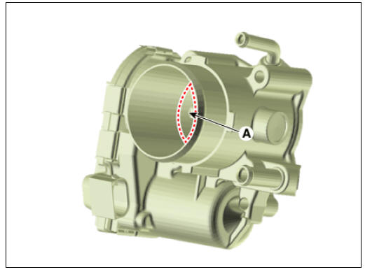
- Clean the pollutant in the throttle body with a soft cloth moistened by cleaning fluid.

Warning
- Do not spray cleaning fluid directly onto ETC module. Instead, use a lint-free cloth moistened by cleaning fluid.
- Be careful not to clean off the coating fluid around the shaft. If coating fluid is removed, idling control failure may occur from inflow of foreign substances or excessive air leakage.
- After cleaning, reinstall the ETC module and then perform the ETC module
learning procedure.
(Refer to Engine Control System - "ETC System" - Adjustment)
Fail-Safe Mode

Warning
When throttle value is stuck at 7º, engine speed will be limited to below 1,500 rpm and vehicle speed to maximum of 40 - 50 km/h (25 - 31 mph).
Specification

READ NEXT:
 Manifold Absolute Pressure Sensor (MAPS)
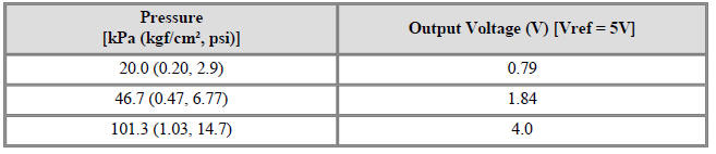
Description
Manifold Absolute Pressure Sensor (MAPS) is a speed-density type sensor
installed on the surge tank.
It senses absolute pressure of the surge tank and transfers the analog signal
proportional to the pressure
to the ECM. By using
Mass Air Flow Sensor (MAFS)
Description
MAFS uses a sensing element made of a hot-film to measure the mass of intake
air entering the engine
and to send the signal to the ECM.
A large amount of intake air represents acceleration or high load conditions
while a small am
Intake Air Temperature Sensor (IATS)
Specification
Description
Mounted inside the Manifold Absolute Pressure Sensor, Intake Air Temperature
Sensor (IATS) detects
the intake air temperature.
To precisely calculate the amount of air, correction of the air temperature is
requ
SEE MORE:
Interior overview
Left-hand drive (Kia NIRO Hybrid)
Right-hand drive (Kia NIRO Hybrid)
Inside door handle
Seat position memory system
Outside rearview mirror folding switch
Outside rearview mirror control switch
Central door lock/unlock switch
Battery Pack Assembly Repair procedures
Warning
Be sure to read and follow the "General Safety Information and
Caution" before doing any work related with the high
voltage system. Failure to follow the safety instructions may result in
serious electrical injuries.
Be sure to
Categories
- Home
- KIA Niro EV, Hybrid - Second generation - (SG2) (2021-2024) - Owner's manual
- Kia Niro - First generation - (DE) (2017-2022) - Service and Repair Manual
- Contact Us