KIA Niro: Cylinder Head Repair procedures
Removal
Engine removal is not required for this procedure.
Warning
- Be sure to read and follow the "General Safety Information and Caution" before doing any work related with the high voltage system. Failure to follow the safety instructions may result in serious electrical injuries.
- Be sure to shut off the high voltage circuit according to the "High Voltage Shut-off Procedures" before doing any work related with the high voltage system to avoid serious electrical injuries.
Warning
- Use fender covers to avoid damaging painted surfaces.
- To avoid damaging the cylinder head, wait until the engine coolant temperature drops below normal temperature (20ºC (68ºF)) before removing it.
- When handling a metal gasket, be careful not to fold the gasket or damage the contacting surface of the gasket.
- To avoid damage, unplug the wiring connectors carefully while holding the connector portion.
- Turn the crankshaft pulley so that the No. 1 piston is at TDC (Top dead center).
Warning
Mark all wiring and hoses to avoid misconnection.
- Shut off the High Voltage circuit.
(Refer to Engine Mechanical System - "High Voltage Shutoff Procedure")
- Remove the air cleaner assembly.
(Refer to Intake and Exhaust System - "Air Cleaner")
- Remove the engine room under cover.
(Refer to Engine and Transaxle Assembly - "Engine Room Under Cover")
- Drain the engine coolant.
(Refer to Cooling System - "Coolant")
- Drain the inverter coolant.
(Refer to Hybrid Motor System - "Coolant")
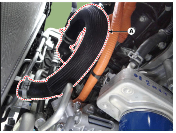
- Disconnect the radiator upper hose (A).
- Disconnect the radiator lower hose (A).
- Remove the hybrid power control unit (HPCU) and tray.
(Refer to Hybrid Control System - "Hybrid Power Control Unit (HPCU)")
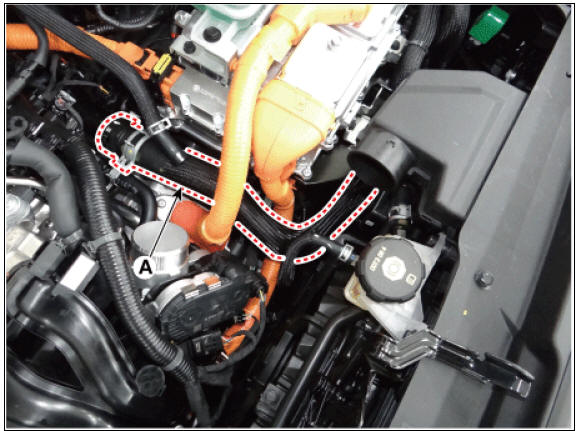
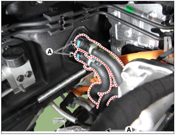
- Disconnect the reservoir tank coolant hose (A).
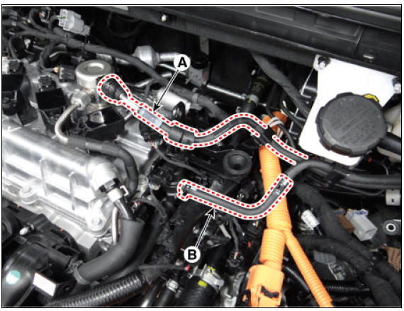
- Disconnect the hybrid starter generator (HSG) coolant hose (A).
- Disconnect the electric water pump (EWP) coolant hose (A).
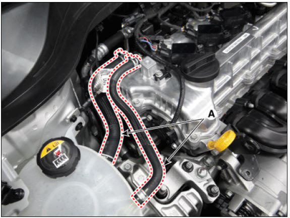
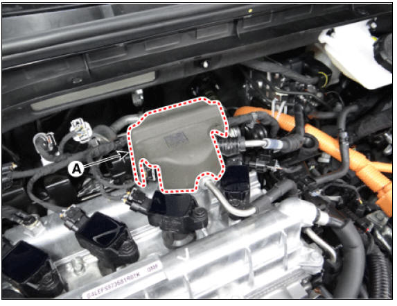
- Remove the high pressure fuel pump foam (A).
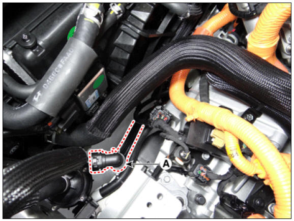
- Disconnect the fuel hose (A) and purge control solenoid valve (PCSV) hose (B).
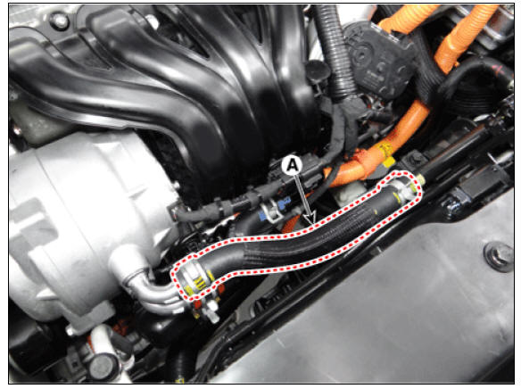
- Disconnect the heater hose (A).
- Remove the front muffler.
(Refer to Intake and Exhaust System - "Muffler")
- Remove the water temperature control assembly and heater pipe.
(Refer to Cooling System - "Water Temperature Control Assembly")
- Remove the intake manifold.
(Refer to Intake and Exhaust System - "Intake Manifold")
- Remove the hybrid starter generator (HSG).
(Refer to Hybrid Motor System - "Hybrid Starter Generator (HSG)")
- Remove the electric EGR control valve.
(Refer to Engine Control/Fuel System - "Electric EGR Control Valve")
- Remove the spark plugs.
(Refer to Engine Electrical System - "Spark Plug")
- Remove the cylinder head cover.
(Refer to Cylinder Head Assembly - "Cylinder Head Cover")
- Remove the exhaust manifold.
(Refer to Intake and Exhaust System - "Exhaust Manifold")
- Remove the timing chain.
(Refer to Timing System - "Timing Chain")
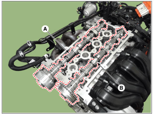
- Remove the CVVT & camshaft.
(1) Remove the camshaft front bearing cap and camshaft bearing cap in the sequence shown.

(2) Remove the exhaust CVVT & camshafts (A) and intake camshaft (B).
- Remove the hydraulic lash adjuster (HLA) (A) and the swing arm (B).

Warning
The HLA and swing arm should be kept together in pair during storage after removal and reinstallation.
- Remove the cylinder head.
(1) Using triple square wrench, uniformly loosen and remove the 10 cylinder head bolts, in several passes, in the sequence shown. Remove the 8 cylinder head bolts and plate washers.

Warning
Removing bolts in an incorrect order may result in head warpage or cracks.
(2) Lift the cylinder head (A) from the dowels on the cylinder block and place the cylinder head on wooden blocks on a bench.

Warning
Be careful not to damage the contacting surfaces of the cylinder head and cylinder block.
(3) Remove the cylinder head gasket (A).

Disassembly
Warning
Identify valves and valve springs as they are removed so that each item can be reinstalled in its original position.
- Remove the valves.
(1) Using the SST (09222-3K000, 09222-3K100), compress the valve spring and remove the retainer lock (A).
Warning
When installing the SST, insert the front support directly into the bolt hole on the cylinder head.
(2) Remove the spring retainer (B).
(3) Remove the valve spring (C).
(4) Remove the valve (D).
(5) Using needle-nose pliers, remove the valve stem seal (E).

Warning
Do not reuse the valve stem seals.
Inspection
READ NEXT:
 Cylinder Head
Inspect for flatness.
Using a precision straight edge and feeler gauge, measure the contacting
surface of the cylinder block and check
the manifolds for warpage.
If the flatness is greater than maximum, replace the cylinder head.
Fla
HLA (Hydraulic Lash Adjuster)
With the HLA filled with engine oil, hold A and press B by hand.
If B moves, replace the HLA.
Reassembly
Warning
Thoroughly clean all parts to be assembled.
Before installing the parts, apply fresh engine oil to all
sliding
SEE MORE:
Fuel Pressure Regulator Repair procedures | Fuel Line Repair procedures
Removal
Remove the fuel pump.
(Refer to Fuel Delivery System - "Fuel Pump")
Disconnect the fuel pump motor connector (A) and fuel sender connector (B).
Lift the fixing hook (A) by using a comm
Front Door Latch
Front door latch
Replacement
Remove the front door module.
(Refer to Front Door - "Front Door Module")
Disconnect the front door latch rod (A) and extension wiring clip (B).
Remove the front door latch (B) after
Categories
- Home
- KIA Niro EV, Hybrid - Second generation - (SG2) (2021-2024) - Owner's manual
- Kia Niro - First generation - (DE) (2017-2022) - Service and Repair Manual
- Contact Us