KIA Niro: Smart Key Repair procedures, Smart Key Unit
Adjustment
Smart Key Code Saving
- Connect the VCI II in driver side crash pad lower panel, turn the power on KDS.
- Select the vehicle model and then do "Smart key code saving".
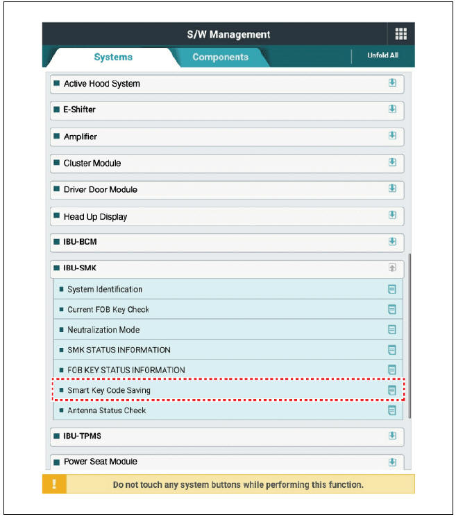
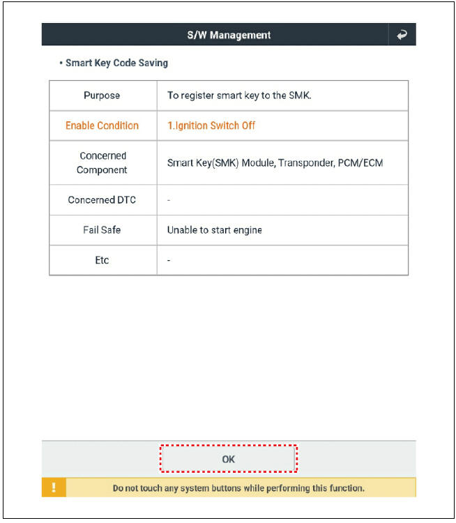
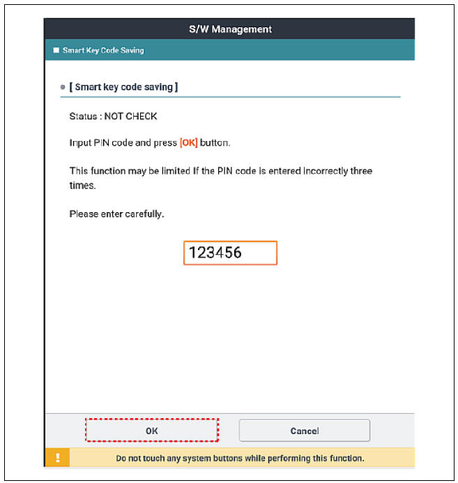
- After selecting "Smart Key Code Saving" menu, push "OK" button, then the screen will be shown as below.
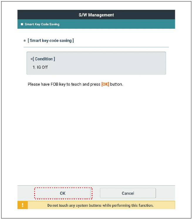
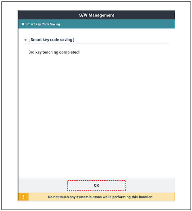
- After teaching new smart key, push "OK" button.
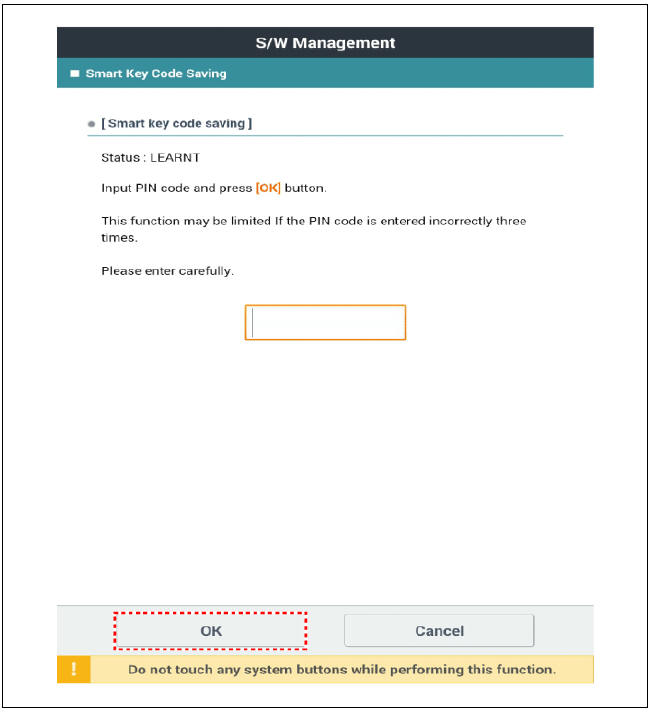
- Input the "Pin code" for first key teaching.
- Confirm the message "First key teaching completed".
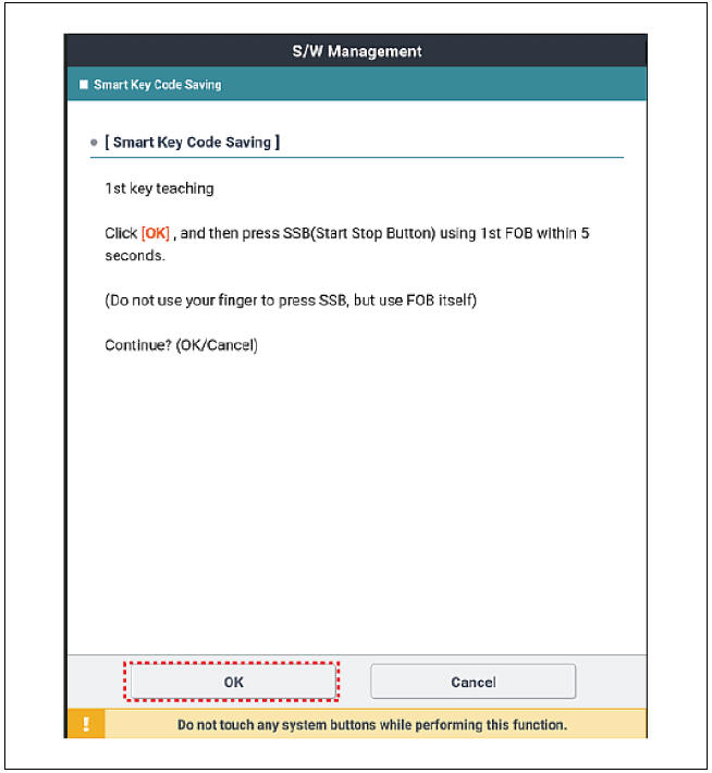
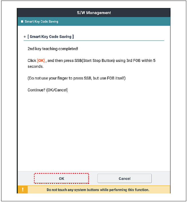
- Press the SSB with smart key within 5 sec after pressing "OK".
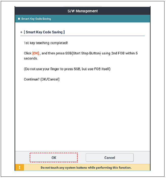
- Confirm the message "Second key teaching completed".
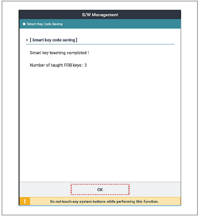
- Then the screen will be shown as below when key teaching process is completed.
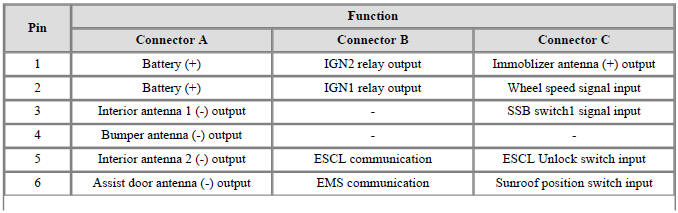
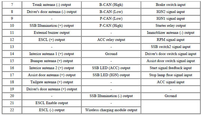
Smart Key Unit
Smart Key Unit Components and components location
Smart Key Unit Repair procedures
Removal
Smart Key Unit
- Remove the BCM.
(Refer to Body Control Module - "Removal")
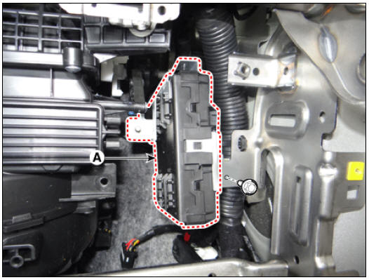
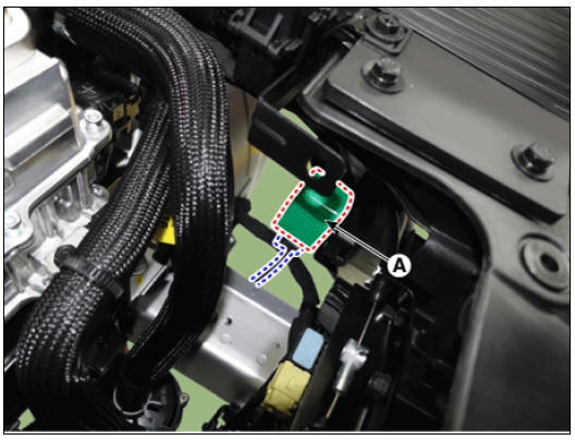
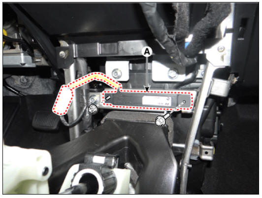
- Remove the smart key unit (A) by loosening the bolt.
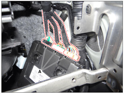
- Disconnect the connectors (A) from the smart key unit.
Buzzer
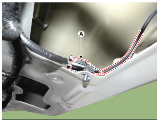
- After removing the buzzer (A), disconnect the connector from the buzzer.
Tailgate Lid Handle
- Remove the tailgate latch.
(Refer to Body - "Tailgate Latch")
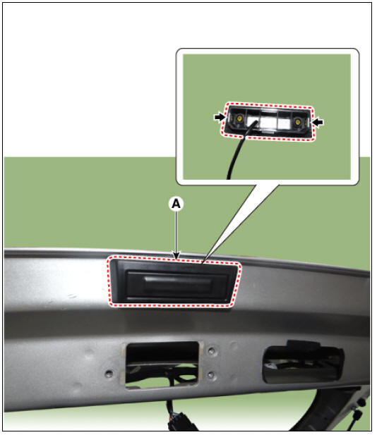
- Disconnect the connector (A) and remove the wiring fixing clip.
- Remove the tailgate lid handle (A) after pushing the hooks.
Door Outside Handle
- Remove the front door outside handle.
(Refer to Body - "Front Door Outside Handle")
Installation
- Install in the reverse order of removal.
Inspection
Smart Key Unit
- Inspect the smart key unit by using the KDS.
(Refer to Smart Key System - "Smart Key Diagnostic")
Buzzer
- After removing the buzzer (A), disconnect the connector from the buzzer.

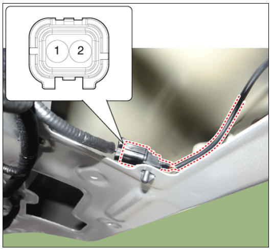
- Test the buzzer by connecting battery power to the terminal 2 and ground the terminal 1.
Tailgate Lid Handle
- Remove the tailgate lid trim.
(Refer to Body - "Tailgate Trim")
- Check for continuity between the terminals.
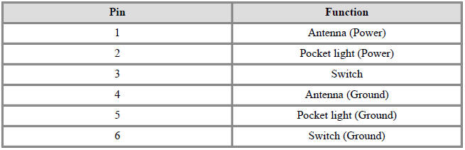
Door Outside Handle
- Remove the front door outside handle.
(Refer to Body - "Front Door Outside Handle")
- Disconnect the front door outside handle connector and then check for continuity between terminals No 3 and No 6.
Removal
Interior Antenna 1
- Remove the floor console assembly.
(Refer to Body - "Floor Console Assembly")
- Remove the interior antenna 1 (A) by loosening the nut and bolt after disconnecting the connector.
Interior Antenna 2
- Remove the floor console assembly.
(Refer to Body - "Floor Console Assembly")
- Remove the interior antenna 2 (A) by loosening the screws after disconnecting the connector.
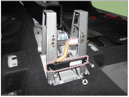
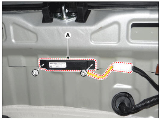
Tailgate Antenna
- Remove the rear transverse trim.
(Refer to Body - "Rear Transverse Trim")
- Remove the tailgate antenna (A) by loosening the nuts after disconnecting the connector.
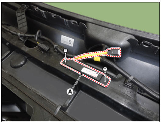
Rear Bumper Antenna
- Disconnect the negative (-) battery terminal.
- Remove the rear bumper antenna (A) by loosening the screws after disconnecting the connector.
Installation
- Install in the reverse order of removal.
Inspection
- Inspect the antenna by using the KDS.
(Refer to Smart Key System - "Smart Key Diagnostic")
READ NEXT:
 Smart Key Diagnostic Repair procedures
Inspection
In the body electrical system, failure can be quickly diagnosed by using
the vehicle diagnostic system (KDS).
The diagnostic system (KDS) provides the following information.
(1) Self diagnosis : Checking failure and code number
Sunroof
Sunroof / Components And Components Location
Sunroof
Sunroof switch
Sunroof motor & controller
Description
The Sunroof is quiped with a one touch on/off switch to open and close the
glass, and it has an ANTIPINCH
function which
SEE MORE:
Electronic Stability Control (ESC)
Electronic Stability Control (ESC)
Electronic Stability Control (ESC) is
designed to stabilize the vehicle during
cornering maneuvers.
ESC is not a substitute for safe driving
practices. Factors including speed, road
conditions and driver ste
Drive Belt Tensioner Repair procedures
Removal and
Installation
Remove the drive belt.
(Refer to Drive Belt System - "Drive Belt")
Remove the mechanical tensioner (A).
Tightening torque :
18.6 - 23.5 N*m (1.9 - 2.4 kgf*m, 13.7 - 17.4 lb*ft)
Remove the hydr
Categories
- Home
- KIA Niro EV, Hybrid - Second generation - (SG2) (2021-2024) - Owner's manual
- Kia Niro - First generation - (DE) (2017-2022) - Service and Repair Manual
- Contact Us