KIA Niro: Drive Belt Tensioner Repair procedures
Removal and
Installation
- Remove the drive belt.
(Refer to Drive Belt System - "Drive Belt")
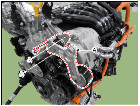
- Remove the mechanical tensioner (A).
Tightening torque : 18.6 - 23.5 N*m (1.9 - 2.4 kgf*m, 13.7 - 17.4 lb*ft)
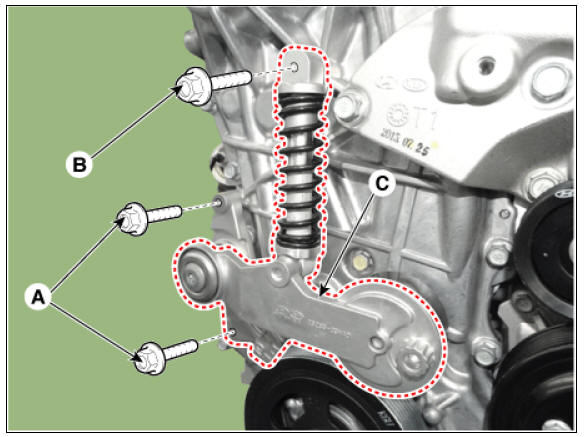
- Remove the hydraulic tensioner.
(1) Check that the hydraulic tensioner spring is compressed.
(2) Unfasten the hydraulic tensioner mounting bolt (A).
(3) Unfasten the hydraulic tensioner center bolt (B).
(4) Remove the hydraulic tensioner mounting bolt (A).
(5) Remove the hydraulic tensioner (C).
Tightening torque : 27.5 - 31.4 N*m (2.8 - 3.2 kgf*m, 20.3 - 23.1 lb*ft)
- Install in the reverse order of removal.
Inspection
Check the belt tensioner for excessive dust, crack, and damage. Replace if necessary.
Crankshaft Damper Pulley Repair procedures
Removal and
Installation
- Remove the RH front wheel.
(Refer to Suspension System - "Wheel")
- Remove the engine room under cover.
(Refer to Engine and Transaxle Assembly - "Engine Room Under Cover")
- Remove the drive belt.
(Refer to Drive Belt System - "Drive Belt")
- Remove the crankshaft damper pulley (A).
Tightening torque : (64.7 - 71.6 N*m (6.6 - 7.3 kgf*m, 47.7 - 52.8 Ib*ft)) + (39 - 41º)

Warning
Using the SST (09231-2M100, 09231-2J210) to hold the crankshaft
damper pulley. 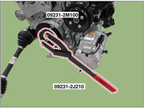
- Install in the reverse order of removal.
READ NEXT:
 Engine And Transaxle Assembly
Engine Room Under Cover Repair procedures
Removal
Engine room under cover.
Remove the engine room under cover (A).
Tightening torque :
3.9 - 5.9 N*m (0.4 - 0.6 kgf*m, 2.9 - 4.3 lb*ft)
Install in the reverse order of removal.
Engine Mounting Repair Procedures
Engine Mounting Components and components location
Transaxle mounting bracket
Roll rod bracket
Engine mounting bracket
Engine mounting support bracket
Engine Mounting Repair Procedures
Removal and
Installation
Engine Mounting Brac
Engine And Transaxle Assembly Repair procedures
Removal
Warning
Be sure to read and follow the "General Safety Information and
Caution" before doing any work related with
the high voltage system. Failure to follow the safety instructions may
result in serious electrical injuries.
Be
SEE MORE:
Limitations of Parking Collision- Avoidance Assist
Parking Collision-Avoidance Assist may
not assist braking or warn the driver
even if there are pedestrians or objects
under the following circumstances:
There is a problem with the vehicle
Any non-factory equipment or accessory
is installe
Multi Fuse
(Multi Fuse A, B)
Disconnect the negative (-) battery terminal.
Remove the power cable terminal (A) after loosening the nut from the
engine room fuse & relay
box.
Remove the multi fuse A (A) after pushing the hook.
Remo
Categories
- Home
- KIA Niro EV, Hybrid - Second generation - (SG2) (2021-2024) - Owner's manual
- Kia Niro - First generation - (DE) (2017-2022) - Service and Repair Manual
- Contact Us