KIA Niro: Tire Repair procedures
Warning
Using tires and wheel other than the recommended sizes could cause unusual handling characteristics and poor vehicle control, resulting in a serious accident.
- Measure the tread depth of the tires.
Tread depth (limit) : 1.6 mm (0.0630 in.)
- If the remaining tread depth (A) is less than the limit, replace the tire.
Warning
When the tread depth of the tires is less than 1.6 mm (0.0630 in), the wear indicators (B) will appear.
Tire Rotation
Checking For Pull And Wander
If the steering pulls to one side, rotate the tires according to the following wheel rotation procedure.
- Rotate the front right and front left tires, and perform a road test in order to confirm vehicle stability.
- If the steering pulls to the opposite side, rotate the front and rear tires, and perform a road test again.
- If the steering continues to pull to one side, rotate the front right and left tires again, and perform a road test.
- If the steering continues to pull to the opposite side, replace the front wheels with new ones.
Removal
- Remove valve core and deflate the tire.
- Remove the side of the tire bead area from the wheel using tire changing machine.

Warning
- The tire bead should be broken approx. 90º from the valve side of the wheel. The bead breaker should not be set too deep.
- Avoid tire/tool contact with the valve on dismount.
- Dismount should end near the valve.
- Rotate the wheel clockwise.

Installation
- Apply tire soap or lubrication to the top and bottom tire beads.
- To fit the bottom bead, position the valve at the 5 o'clock position relative to the head on the tire changing machine.
- Place the tire on the rim so the bottom bead touches the edge of the rim past the valve (6 o'clock). Rotate the rim clockwise, and push down on the tire at the 3 o'clock position to fit bottom bead.
- After bottom bead is on tire, rotate the rim until the valve is at the 5 o'clock position relative to the head on the tire changing machine. Push down on the tire at the 3 o'clock position and rotate the rim clockwise to fit the top bead.
- Inflate the tire until both beads seat.
Tire presuure : 250 - 257 kPa (36 - 37 psi)

Wheel Repair procedures
Hub nut tightening sequence
Tighten the hub nuts in the following sequence.
Tightening torque: 88.3 - 107.9 N*m (9.0 - 11.0 kgf*m, 65.1 - 79.6 lb*ft)

Warning
When using an impact gun, final tightening torque should be checked using a torque wrench.
Run out inspection
- Jack up the vehicle.
- Measure the wheel run-out by using a dial indicator as shown below.
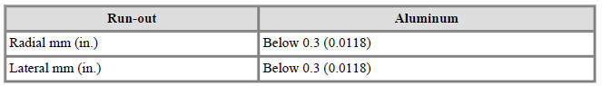
- If measured value exceeds the standard value, replace the wheel

READ NEXT:
 Alignment Repair procedures
Front wheel alignment
Warning
When using a commercially available computerized wheel alignment
equipment to inspect the front wheel
alignment, always position the vehicle on a level surface with the front wheels
facing straight ahead.
Prior
Tire Pressure Monitoring System
Tire Pressure Monitoring System / Components And Components Location
BCM (TPMS)
TPMS Sensor (FL)
TPMS Sensor (RL)
TPMS Sensor (RR)
TPMS Sensor (FR)
Description
TREAD Lamp
Tire Under Inflation / Leak Warning.
Turn on c
Troubleshooting - Tire Pressure Monitoring System
TPMS Inspection method
Inspection
Warning
Find the inspection number by referring to the table above.
The following content is irrelevant of the inspection procedure.
Warning lamp types
Stays on without blinking : Low pressure tir
SEE MORE:
Rear Axle Assembly / Rear Hub - Carrier
Components
Disc
Dust cover
Rear hub
Rear Knuckle
Rear Hub - Carrier / Repair Procedures
Removal
Remove the tire (A).
Tightening torque :
107.9 - 127.5 N*m (11.0 - 13.0 kgf*m, 79.6 - 94.0 lb*ft)
Warning
Be careful not t
Emission control system (if equipped)
Kia NIRO Hybrid
The emission control system of your
vehicle is covered by a written limited
warranty. Please see the warranty information
contained in the Warranty &
Maintenance book in your vehicle.
Your vehicle is equipped with an emiss
Categories
- Home
- KIA Niro EV, Hybrid - Second generation - (SG2) (2021-2024) - Owner's manual
- Kia Niro - First generation - (DE) (2017-2022) - Service and Repair Manual
- Contact Us