KIA Niro: Rear Stabilizer Bar Repair procedures
Removal
- Disconnect the battery negative cable.
- Remove the wheel and tire.
Tightening torque: 107.9 - 127.5 N*m (11.0 - 13.0 kgf*m, 79.6 - 94.0 lb*ft)

Warning
Be careful not to damage the wheel nuts when removing the wheel and tire.
- Loosen the rear stabilizer link bolt (A).
Tightening torque: 19.6 - 29.4 N*m (2.0 - 3.0 kgf*m, 14.5 - 21.7 lb*ft)

Warning
Set up the transmission jack under the lower arm in order to remove the shock absorber in no-load condition.
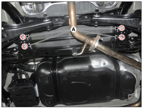
- Loosen the bolts (A) and then remove the rear stabilizer bar.
Tightening torque: 44.1 - 53.9 N*m (4.5 - 5.5 kgf*m, 32.5 - 39.8 lb*ft)
- Install in the reverse order of removal.
Inspection
- Check the rear stabilizer bar for deformation.
- Check the rear stabilizer link ball joint for damage.
Rear Assist Arm Repair procedures
Removal
- Disconnect the battery negative cable.
- Remove the wheel and tire.
Tightening torque: 107.9 - 127.5 N*m (11.0 - 13.0 kgf*m, 79.6 - 94.0 lb*ft)

Warning
Be careful not to damage the wheel nuts when removing the wheel and tire.
- Loosen the bolts (A,B) and then remove the rear assist arm.
Tightening torque: (A) 137.3 - 156.9 N*m (14.0 - 16.0 kgf*m, 101.3 - 115.7 lb*ft) (B) 107.9 - 117.7 N*m (11.0 - 12.0 kgf*m, 79.6 - 86.8 lb*ft)

Warning
Set up the transmission jack under the lower arm in order to remove the shock absorber in no-load condition.
- Install in the reverse order of removal.
- Check the wheel alignment.
(Refer to Suspension System - "Alignment")
Inspection
- Check the bushing for wear and deterioration.
- Check all bolts and nut.
READ NEXT:
 Trailing Arm Repair procedures
Removal
Disconnect the battery negative cable.
Remove the wheel and tire.
Tightening torque:
107.9 - 127.5 N*m (11.0 - 13.0 kgf*m, 79.6 - 94.0 lb*ft)
Warning
Be careful not to damage the wheel nuts when removing the wheel and
tire.
Rear Cross Member Repair procedures
Removal
Disconnect the battery negative cable.
Remove the wheel and tire.
Tightening torque:
107.9 - 127.5 N*m (11.0 - 13.0 kgf*m, 79.6 - 94.0 lb*ft)
Warning
Be careful not to damage the wheel nuts when removing the wheel and
tire.
SEE MORE:
Mode Control Actuator Repair procedures
Mode Control Actuator Components and components location
Mode control actuator (LH)
Mode control actuator (RH)
Description
Located in the heater unit, the mode control actuator adjusts the position of
the mode door by
operating the m
CVVT Oil Control Valve (OCV)
Specification
Bank 1 / Exhaust
Description
Continuous Variable Valve Timing (CVVT) system advances or retards the valve
timing of the intake
and exhaust valve in accordance with the ECM control signal which is calculated
by the engine spe
Categories
- Home
- KIA Niro EV, Hybrid - Second generation - (SG2) (2021-2024) - Owner's manual
- Kia Niro - First generation - (DE) (2017-2022) - Service and Repair Manual
- Contact Us