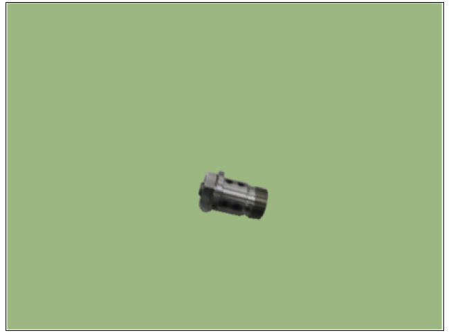
KIA Niro: CVVT Oil Control Valve (OCV)
Specification
Bank 1 / Exhaust

Description
Continuous Variable Valve Timing (CVVT) system advances or retards the valve
timing of the intake
and exhaust valve in accordance with the ECM control signal which is calculated
by the engine speed
and load.
By controlling CVVT, the valve overlap or underlap occurs, which in turn
improves fuel efficiency,
reduces exhaust gases (NOx, HC) and improves engine performance by reducing
pumping loss,
generating internal EGR effect, improving combustion stability, improving
volumetric efficiency and
increasing expansion work.
This system consists of
- the CVVT Oil Control Valve (OCV) which supplies the engine oil to the
cam phaser or cuts the
engine oil from the cam phaser in accordance with the ECM PWM (Pulse With Modulation) control
signal, - the CVVT Oil Temperature Sensor (OTS) which measures the engine oil temperature,
- and the Cam Phaser which varies the cam phase by using the hydraulic force of the engine oil.
The engine oil released from the CVVT oil control valve varies the cam phase
in the direction (Intake
Advance/Exhaust Retard) or opposite direction (Intake Retard/Exhaust Advance) of
the engine rotation
by rotating the rotor connected with the camshaft inside the cam phaser.
Bank1 / Intake
Bank 1 / Exhaust
Circuit Diagram

Harness Connector
OCV (B1/EX)

Inspection
- Switch "OFF" the ignition.
- Disconnect the OCV connector.
- Measure resistance between the OCV terminals 1 and 2.
- Check that the resistance is within the specification.
Specification: 9.4 ~ 10.4 Ω (20ºC(68ºF))
CVVT Oil Control Valve (OCV) Repair procedures
Removal
CVVT Oil Control Valve
CVVT Oil Control Valve (Intake)
- Switch "OFF" the ignition and disconnect the negative (-) battery terminal.
- Remove the variable force solenoid.
(Refer to Engine Control System - " Variable Force Solenoid")
- Remove the cylinder head cover.
(Refer to Engine Mechanical System - "Cylinder Head Cover")
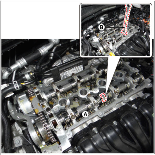
- Remove the CVVT oil control valve (A) using a socket & wrench (B).
CVVT oil control valve center bolt : (47.1 - 52.0 N.m (4.8 - 5.3 kgf.m, 34.7 - 38.3 lb-ft)) + (25 - 31º)

Warning
- To prevent impurities from entering intake OCV & center bolt, wear rubber gloves.
- When removing the intake OCV & center bolt, place a wrench (B)
at position (A) to prevent the
camshaft from rotating.
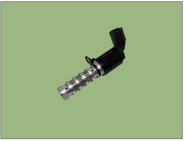
CVVT Oil Control Valve (Exhaust)
- Switch "OFF" the ignition and disconnect the negative (-) battery terminal.
- Remove the air cleaner assembly.
(Refer to Engine Mechanical System - "Air Cleaner")
- OCV connector (A).
- Remove the mounting bolt, and then remove oil control valve from the engine.
CVVT oil control valve mounting bolt : 9.8 - 11.8 N*m (1.0 - 1.2 kgf*m, 7.2 - 8.7 lb*ft)

Installation
Warning
- Install the component to the specified torque.
- Note that internal damage may occur when the component is dropped. If the component has been dropped, inspect before installing.
- Apply engine oil to the valve O-ring.
- To prevent impurities from entering intake OCV & center bolt, wear rubber gloves.
- When installing the intake OCV & center bolt, place a wrench
(B) at position (A) to prevent the
camshaft from rotating.
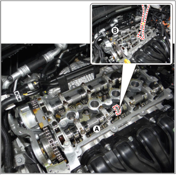
- Install in the reverse order of removal.
READ NEXT:
 Fuel Pressure Control Valve (FPCV)
Specification
Fuel Pressure Control Valve (FPCV) Description
Description
Installed on the high pressure fuel pump, the Fuel Pressure Control Valve
controls the flow of fuel into
the injectors in accordance with the ECM signal calculated ba
Electric EGR Control Valve
Specification
Motor
Position sensor
Electric EGR Control Valve Description and operation
Description
The Electric EGR Control Valve is a solenoid valve installed between the EGR
cooler and the exhaust
line that controls the EGR (Exhaust
Fuel Delivery System
Components
Location
Fuel Tank Assembly
Fuel tank
Fuel pump
Fuel filter
Fuel pressure regulator
Canister
Fuel tank air Filter
Fuel pressure sensor (FPS)
Fuel tank pressure sensor (FTPS)
Fuel level sensor (FLS)
Fuel tank iso
SEE MORE:
Lane Keeping Assist (LKA)
Lane Keeping Assist is designed to help
detect lane markings (or road edges)
while driving over a certain speed. Lane
Keeping Assist will warn the driver if the
vehicle leaves the lane without using the
turn signal, or will automatically ass
Smart Key Repair procedures, Smart Key Unit
Adjustment
Smart Key Code Saving
Connect the VCI II in driver side crash pad lower panel, turn the power on KDS.
Select the vehicle model and then do "Smart key code saving".
After selecting "Smart Key Code
Categories
- Home
- KIA Niro EV, Hybrid - Second generation - (SG2) (2021-2024) - Owner's manual
- Kia Niro - First generation - (DE) (2017-2022) - Service and Repair Manual
- Contact Us