KIA Niro: Power Window Switch
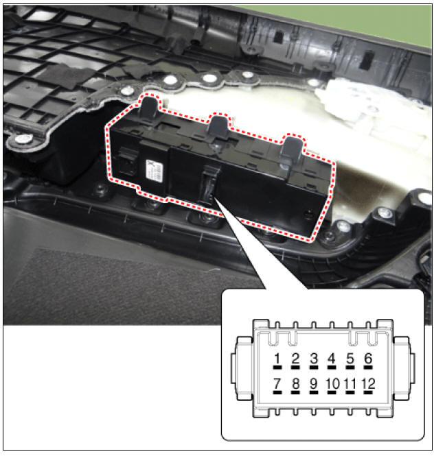
Power Window Switch Components and components location
Power Window Main Switch
Non-IMS type
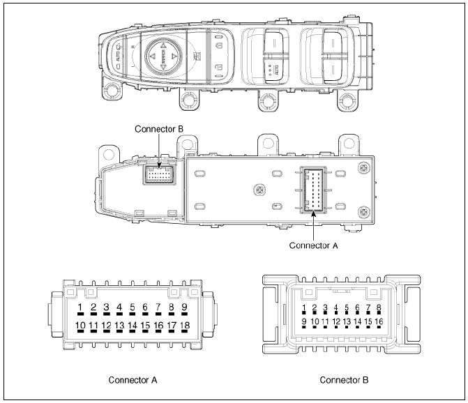

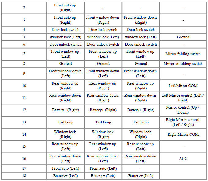
IMS type (DDM : Driver Door Module)
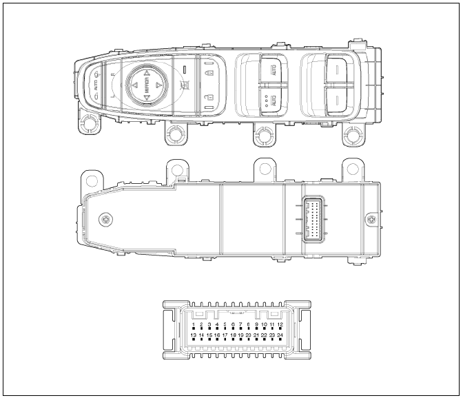
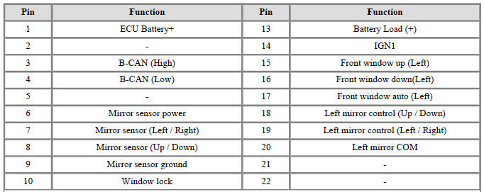

Assist Power Window Switch
Non-IMS type
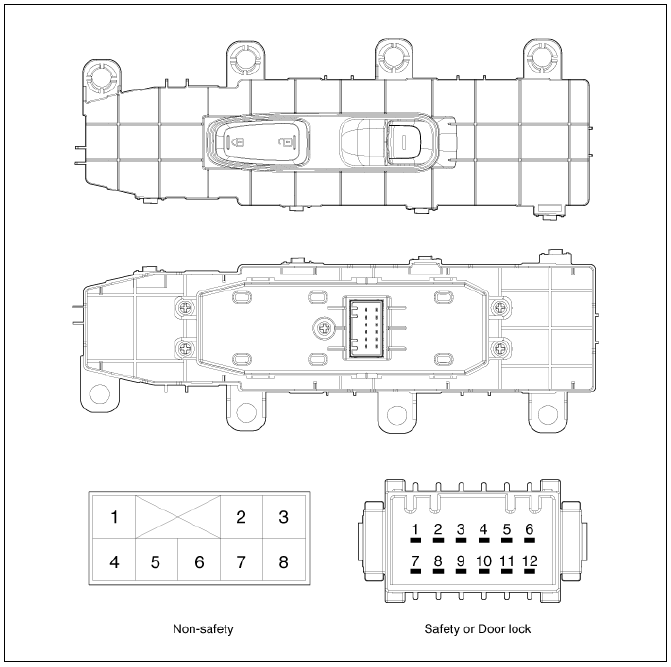

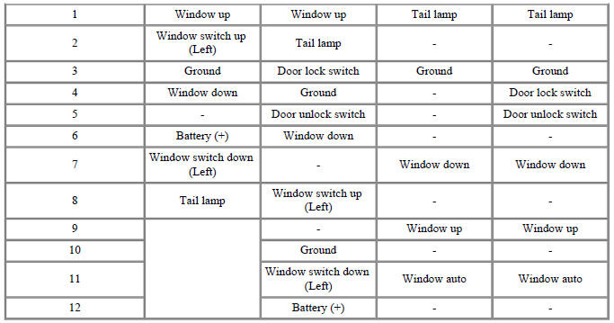
IMS type (ADM : Assist Door Module)
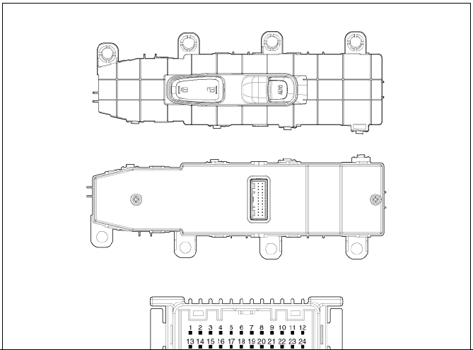

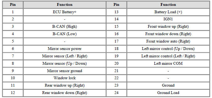
Rear Power Window Switch


Circuit Diagram
Power Window Main Switch
Non-IMS, Manual
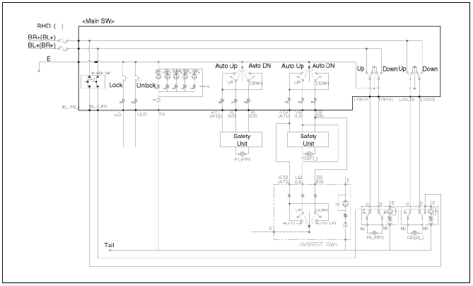
Non-IMS, Safety
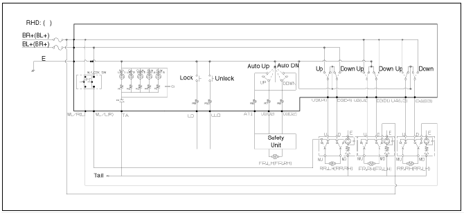
Non-IMS, Auto down
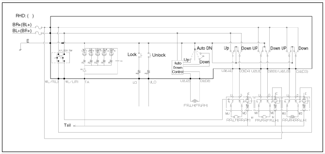
IMS
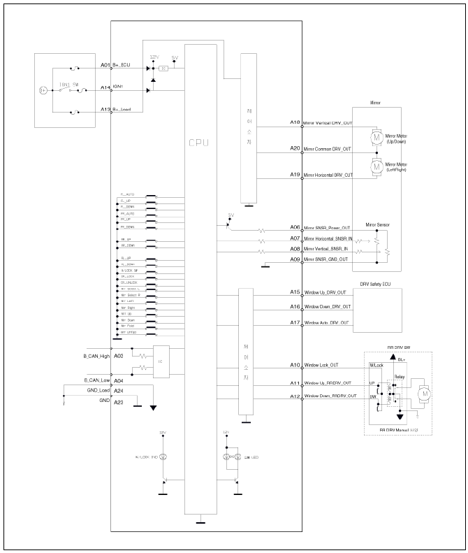
Assist Power Window Switch
Non-IMS, Manual
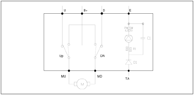
Non-IMS, Manual, Door lock
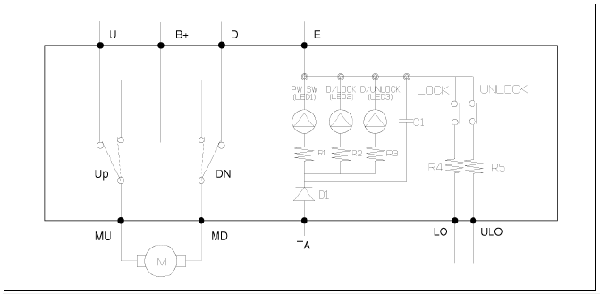
Non-IMS, Safety
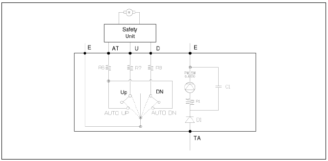
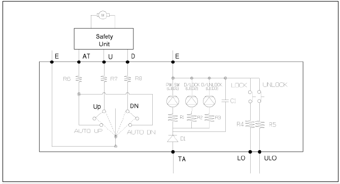
Non-IMS, Safety, Door lock
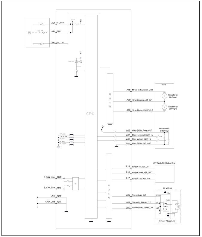
IMS
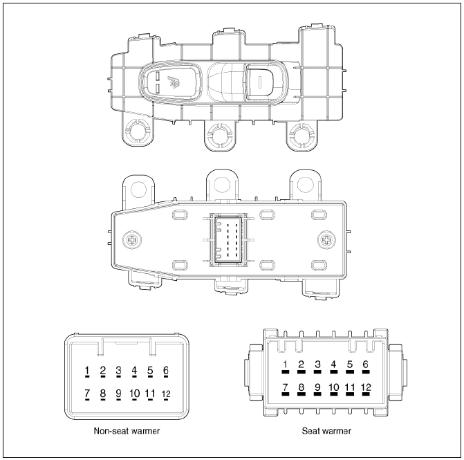
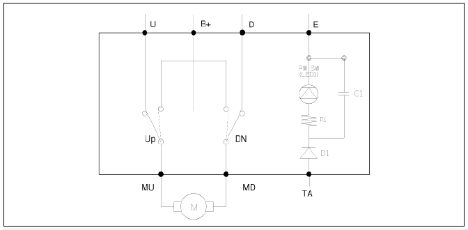
Rear Power Window Switch
Non-seat warmer
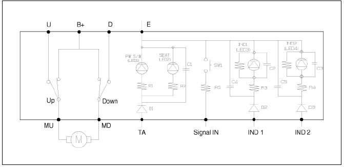
Seat warmer
Power Window Switch Repair procedures
Inspection
IMS (DDM / ADM)
- The body electrical system can be quickly diagnosed for failed parts by using vehicle diagnostic system (KDS).
The diagnostic system (KDS) provides the following information.
(1) Self diagnosis : Checks and displays the failure code (DTC).
(2) Current data : Checks the system input/output data state.
(3) Actuation test : Checks the system operating condition.
(4) Additional function : Other controls such as the system option and zero point.
- Select the 'Car model' and the system to be checked in order to check the vehicle with the tester.
- Select the 'Body Control Module (BCM)' to check the driver seat or assist door module (DDM/ ADM).
- Select the "Current Data" menu to check the current state of the
input/output data.
The input/output data for the sensors corresponding to the driver seat or assist door module (DDM/ ADM) can be checked.
Non-IMS
Power Window Main Switch
- Remove the front left door trim.
(Refer to Body - "Front Door Trim")
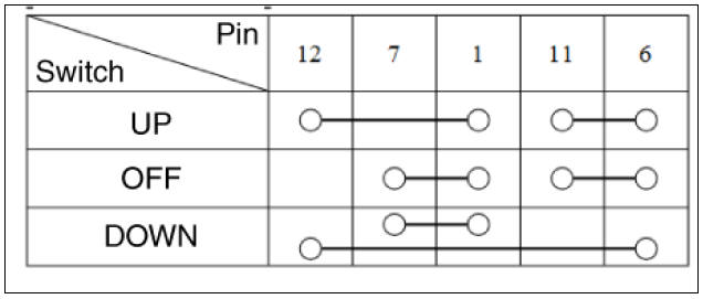
- Check for continuity between the terminals in each switch position according to the table.

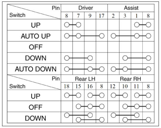
Driver safety
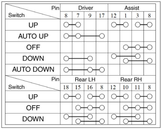
Auto down
Assist Power Window Switch
- Remove the front left door trim.
(Refer to Body - "Front Door Trim")
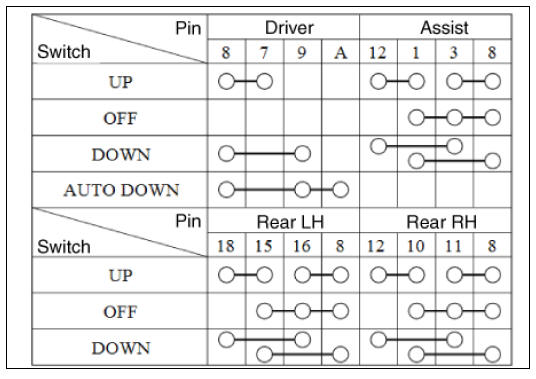
- Check for continuity between the terminals in each switch position according to the table.
Non-safety
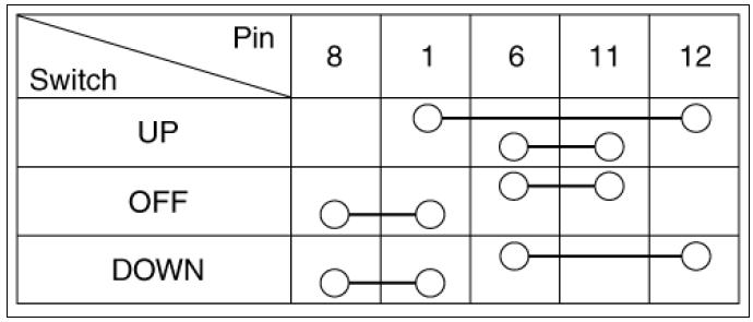
Safety
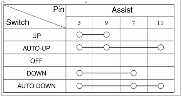
Rear Power Window Switch
- Remove the rear left door trim.
(Refer to Body - "Rear Door Trim")
- Check for continuity between the terminals in each switch position according to the table.
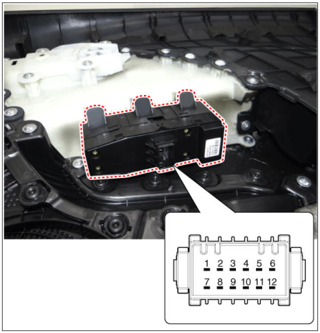
Non-seat
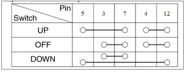
Seat warmer
Removal
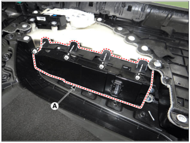
Power Window Main Switch
- Remove the driver front door trim.
(Refer to Body - "Front Door Trim")
- Remove the power window main switch (A) by loosening the screws.
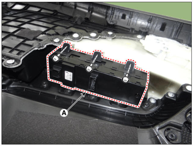
Assist Power Window Switch
- Remove the driver front door trim.
(Refer to Body - "Front Door Trim")
- Remove the assist power window switch (A) by loosening the screws.
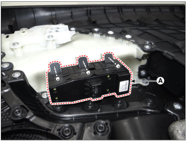
Rear Power Window Switch
- Remove the rear left door trim.
(Refer to Body - "Rear Door Trim")
- Remove the rear power window switch (A) by loosening the screws.
Installation
- Install in the reverse order of removal.
READ NEXT:
 Rear Glass Defogger
Rear Glass Defogger / Components And Components Location
Body control module (BCM)
Rear glass defogger switch
Rear glass defogger
Rear Glass Defogger Printed Heater Repair
Inspection
Warning
Wrap tin foil around the end of the volt
 Power Seat Motor
Power Seat Motor Components and components location
Lumbar support motor (Horizontal)
Slide motor
Reclining motor
Rear height motor
Front tilt motor
Reclining limit switch
Seat cushion switch
Seat back switch
Lumbar support sw
SEE MORE:
 Basic Troubleshooting
Basic Troubleshooting Guide
Customer Problem Analysis Sheet
Basic Inspection Procedure
Measuring Condition of Electronic Parts' Resistance
The measured resistance at high temperature after vehicle
running may be high or low. So all
 Vehicle Information Systems (UVO)
AVN head unit
Crash pad LTE antenna (Wi-Fi, LTE 2)
UVO Keypad
Roof LTE antenna (AM/FM + DMB + GPS + LTE 1)
Description
Vehicle information systems (UVO) based on state-of-the-art IT systems,
safety and security
Warning
The term &
Categories
- Home
- KIA Niro EV, Hybrid - Second generation - (SG2) (2021-2024) - Owner's manual
- Kia Niro - First generation - (DE) (2017-2022) - Service and Repair Manual
- Contact Us
