KIA Niro: Rear Glass Defogger
Rear Glass Defogger / Components And Components Location
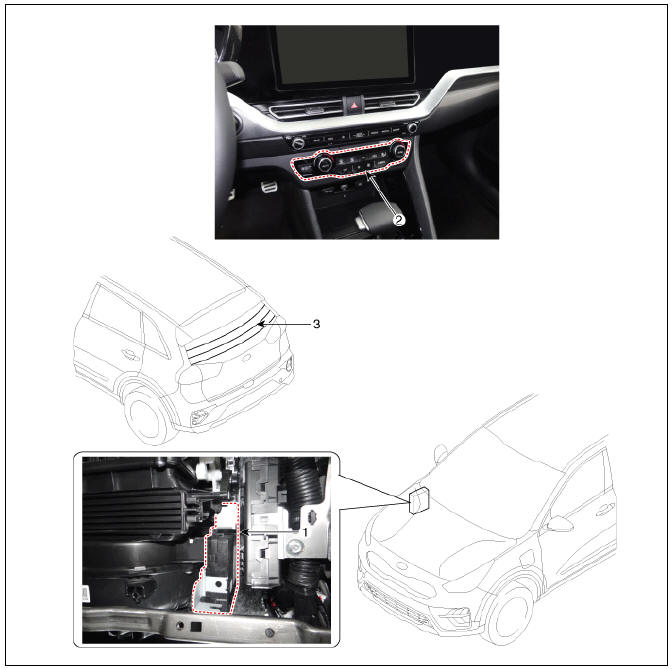
- Body control module (BCM)
- Rear glass defogger switch
- Rear glass defogger
Rear Glass Defogger Printed Heater Repair
Inspection
Warning
Wrap tin foil around the end of the voltmeter test lead to prevent damaging the heater line.
Apply pressure on the tin foil with hand and move the tin foil along the grid line to check for open circuits.
- Turn on the defogger switch and use a voltmeter to measure the voltage of each heater line in the central part of the glass. If the voltmeter indicates 6V for a conductive line, the line of the rear window is considered to be in good condition.
- If a conductive line is burned out within the area between the central part and (+) terminal, the voltmeter will indicate12V.
- If a conductive line is burned out within the area between the central part and (-) terminal, the voltmeter will indicate 0V.
- To check for open circuits, Slowly move the test lead toward the section where open circuits seem to exist. Try to find a point where the voltage turns to 0V. The point where the voltage has changed is the open-circuit point.
- Use an ohmmeter to measure the resistance of each heater line between a terminal and the center of a grid line, and between the same terminal and the center of one adjacent heater line. The section with a broken heater line will have a resistance twice that in other sections. In the affected section, move the test lead to a position where the resistance sharply changes.
Repair of Broken Heater Line Prepare the following items :
- Conductive paint.
- Paint thinner.
- Masking tape.
- Silicone remover.
- Using a thin brush :
Wipe the glass adjacent to the broken heater line, clean with silicone remover and attach the masking tape as shown. Shake the conductive paint container well, and apply three coats with a brush at intervals of about 15 minutes apart. Remove the tape and allow sufficient time for drying before applying power. For a better finish, scrape away excess paint with a knife after the paint has completely dried. (Allow 24 hours).
Rear Glass Defogger Switch Repair procedures
Inspection
- In the body electrical system, failure can be quickly diagnosed by using the vehicle diagnostic system (KDS).
The diagnostic system (KDS) provides the following information.
(1) Self diagnosis : Checking failure and code number (DTC).
(2) Current data : Checking the system input/output data state.
(3) Actuation test : Checking the system operation condition.
(4) Additional function : Controlling other features including system option setting and zero point adjustment.
- Select the 'Car model' and the 'Integrated body control unit (IBU)' to be checked in order to check the vehicle with the tester.
- Select the 'Current Data' menu to search the current state of the input/output data.
- To forcibly actuate the input value of the module to be checked, select option 'Actuation Test'
Removal
- Disconnect the negative battery terminal.
- Remove the heater and A/C control unit.
(Refer to Heating, Ventilation, Air conditioning - "Heater & A/C Control Unit")
Installation
- Install in the reverse order of removal.
READ NEXT:
 Power Seat Motor
Power Seat Motor Components and components location
Lumbar support motor (Horizontal)
Slide motor
Reclining motor
Rear height motor
Front tilt motor
Reclining limit switch
Seat cushion switch
Seat back switch
Lumbar support sw
Power Seat Control Switch Repair procedures
Inspection
Diagnosis With KDS
The body electrical system can be quickly diagnosed for failed parts by
using the vehicle diagnostic system (KDS).
The diagnostic system (KDS) provides the following information.
(1) Self diagnosis : Checks
SEE MORE:
Shift dial SBW type
P (Park)
R (Reverse)
N (Neutral)
D (Drive)
Operation
Depress the brake pedal and turn the
knob to the desired position.
Press P button to shift to P (Park).
Transmission ranges
The indicator in the instrument cluster
Hazardous driving conditions
If driving conditions deteriorate due to
poor weather or road conditions, you
should pay even more attention than
usual.
When hazardous driving conditions are
encountered such as water, snow, ice,
mud, sand, or similar hazards, follow
these su
Categories
- Home
- KIA Niro EV, Hybrid - Second generation - (SG2) (2021-2024) - Owner's manual
- Kia Niro - First generation - (DE) (2017-2022) - Service and Repair Manual
- Contact Us