KIA Niro: Main Fuse Inspection | Checking for Welding in the High Voltage Main Relay
- Turn the ignition switch OFF and disconnect the auxiliary 12V battery negative (-) terminal.
- Shut off the high voltage.
(Refer to Hybrid Control System - "High voltage Shut-off Procedures")
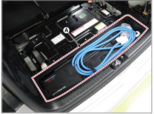
- Remove the center tray trim (A)
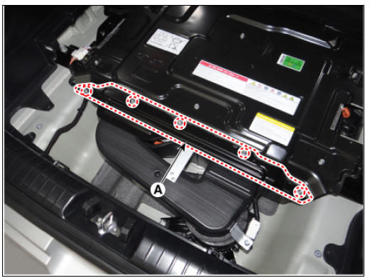
- Remove the sub high voltage battery rear cover (A) after loosening the mounting bolts.
High Voltage Battery Rear Cover mounting bolt : 7.8 - 11.8 N*m (0.8 - 1.2 kgf*m, 5.8 - 8.7 lb*ft)
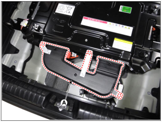
- Remove the rear outlet cooling duct (A) after loosening the mounting bolt.
Rear Outlet Cooling Duct mounting bolt : 7.8 - 11.8 N*m (0.8 - 1.2 kgf*m, 5.8 - 8.7 lb*ft)
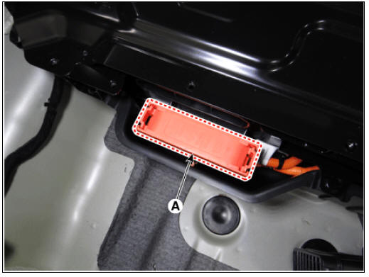
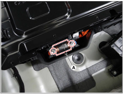
- Remove the main fuse cover (A).
- Remove the main fuse (A) after loosening the mountiong nuts.
Main Fuse mounting nut : 10.98 - 12.94 N*m (1.12 - 1.32 kgf*m, 8.10 - 9.55 lb*ft)
- Measure the resistance of main fuse.

Specification: 1 Ω or less (20ºC(68ºF)
- If the measured resistance is not within the specification, replace the main fuse.
Checking for Welding in the High Voltage Main Relay
Using a Multimeter to measure welding damage
In order to safely remove the battery pack assembly, you must first inspect the high voltage main relay for signs of weld damage.
You can use Gloval Diagnostic System (KDS) service data to detect weld damage in the high voltage main relay.
- Connect the KDS to the self-diagnosis connector (DLC).
- Turn on the ignition.
- Check the BMS weld damage state in the KDS service data.

Using a Multimeter to measure welding damage
Warning
- Be sure to read and follow the "General Safety Information and Caution" before doing any work related with the high voltage system. Failure to follow the safety instructions may result in serious electrical injuries.
- Be sure to read and follow the "High Voltage Shut-off Procedures" before doing any work related with the high voltage system. Failure to follow the safety instructions may result in serious electrical injuries.
- Shut off the high voltage circuit.
(Refer to Hybrid Control System - "High Voltage Shut-off Procedures")
- Remove the rear seat cushion.
(Refer to Body - "Rear Seat Assembly")
- Remove the rear door scuff trim.
(Refer to Body - "Door Scuff Trim")
- Remove the inlet cooling duct.
(Refer to High Voltage Battery Cooling System - "Cooling Duct")
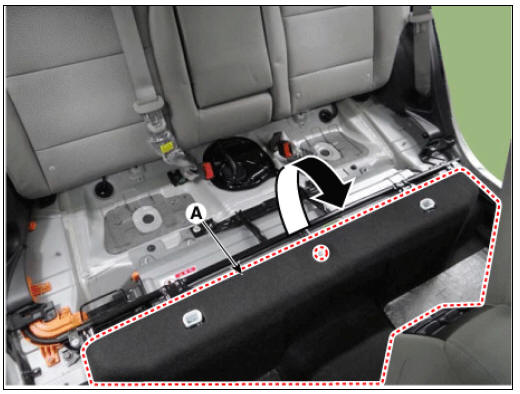
- Open the high voltage battery cushion (A) in the direction of an arrow.
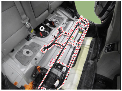
- Remove the upper frame (A) after loosening the mounting bolts and nuts.
- Disconnect the high voltage (+) connector (A) and high voltage (-) connector (B).
- Remove the high voltage cable cover (C) after loosening the mounting bolt.
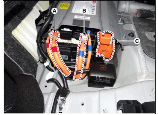
- Measure the high voltage main relay resistance and check for signs of weld damage.
Specification : ¥ Ω (20ºC (68ºF))

Insulation Resistance Inpection
The high voltage isolation used in hybrid systems can be checked using KDS service data or by measuring it directly.
Using KDS service data to check isolation resistance
- Connect the KDS to the self-diagnosis connector (DLC).
- Turn on the ignition.
- Check the isolation resistance in the KDS service data.
Normal insulation resistance range : Around 1.0 MΩ

READ NEXT:
 Measuring insulation resistance using an insulation tester
Warning
Be sure to read and follow the "General Safety Information and
Caution" before doing any work related with the high
voltage system. Failure to follow the safety instructions may result in
serious electrical injuries.
Be sure to
Voltage Check
Warning
Be sure to read and follow the "General Safety Information and
Caution" before doing any work related with the high
voltage system. Failure to follow the safety instructions may result in serious
electrical injuries.
Measu
SEE MORE:
Checking coolant level
Check the condition and connections of
all cooling system hoses and heater
hoses. Replace any swollen or deteriorated
hoses.
The coolant level should be filled
between MAX and MIN (F and L) marks
on the side of the coolant reservoir when
Infotainment system
Using the infotainment/climate switchable controller
Press the button on the switchable controller
to switch between infotainment
system or climate control panel.
Press and hold the button to select the
default mode for the control panel.
Categories
- Home
- KIA Niro EV, Hybrid - Second generation - (SG2) (2021-2024) - Owner's manual
- Kia Niro - First generation - (DE) (2017-2022) - Service and Repair Manual
- Contact Us