KIA Niro: Inverter kit / Body kit
- Remove the battery (-) cable.
- Disconnect the high voltage circuit. (Refer to Generals)
- Use the recovery/reproduction/charging device to recover the coolant.
Warning
- When removing the connector between the vehicle and the compressor, check the connector pins and wiring for damage.
- Use the coolant recovery/charge device exclusively used for the electric compressor to inject the designated coolant and refrigeration oil (POE).
- If the refrigeration oil (PAG) for the ordinary car is injected, the compressor may be damaged or a safetyrelated accident may occur.
- Remove the engine room under cover.
(Refer to Engine Mechanical System - "Engine Room Under Cover")
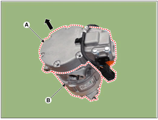
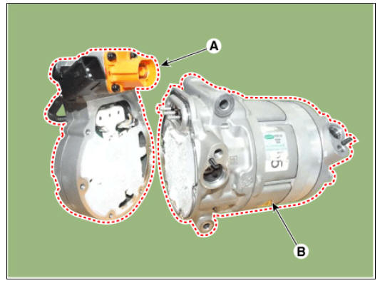
- Disconnect the discharge hose (A) and suction hose (B) after loosening the bolts.
Tightening torque : 7.8 - 11.7 N*m (0.8 - 1.2 kgf*m, 5.7 - 8.6 lb*ft)
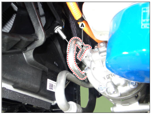
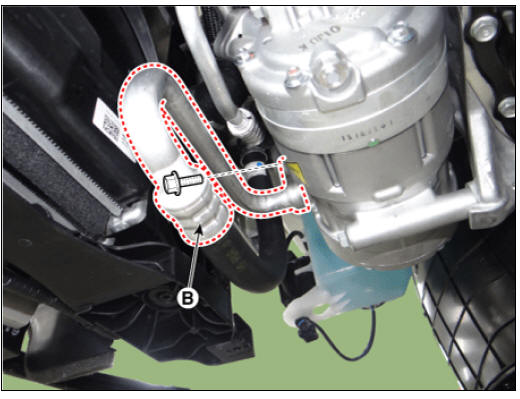
Warning
Plug or cap the lines immediately after disconnecting them to avoid moisture and dust contamination.
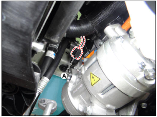
- Disconnect the electric compressor connector (A).
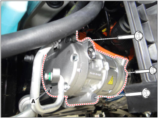
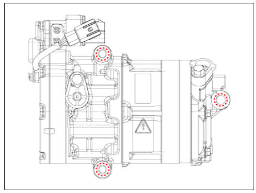
- Loosen the mounting bolts and then remove the compressor assembly (A).
Tightening torque : 20.0 - 32.95 N*m (2.04 - 3.36 kgf.m, 14.75 - 24.30 Ib*ft)
- Disconnect the high voltage connecter (A).
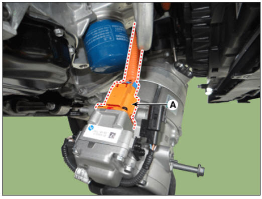
Warning
Pull the locking pin by pressing the lever (A) and remove the
high-voltage connector.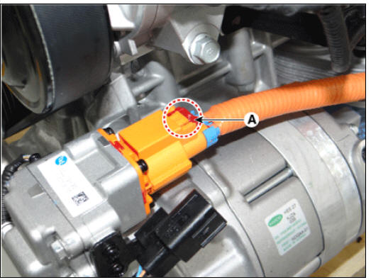
- The inverter/body kit is an electronic component and can be damaged by dust or humidity. It should be moved to the clean room.
Warning
- To prevent the inverter/body kit from getting contaminated, remove dust or dirt from the exterior of the compressor.
- Do not open the package until the inverter/body kit is installed, to prevent the inverter/body kit from getting contaminated.
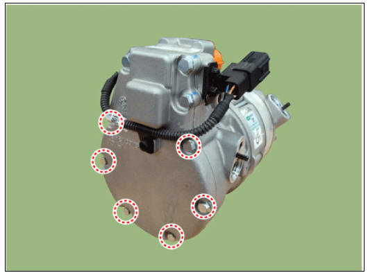
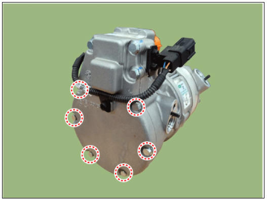
- Remove the bolt that fixes the inverter/body kit.
Warning
- Do not recycle the inverter/body kit fastening bolt.
- Never remove unmarked bolts.
- Remove the inverter kit (A) and body kit (B).
Warning
When removing the inverter/body kit, be careful not to damage, twist
or bend the 3-phase power pin (B). 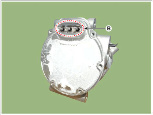
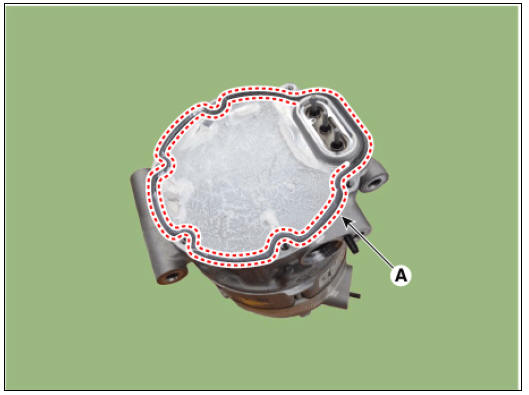
- Remove the inverter/body kit gasket (A).
Warning
- Gaskets prohibit reuse.
- When removing the gasket, prohibit the use of sharp tools and pay attention to damage.
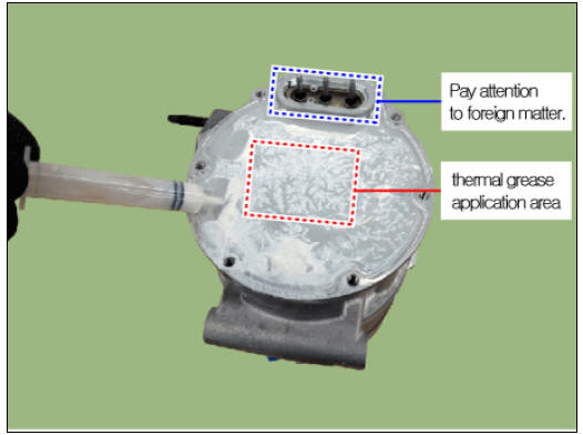
- Apply the thermal grease as in the following before replacing the inverter/body kit.
Applied amount : 3 - 4 g (compressor radiator )
Warning
- When replacing the inverter/body kit, make sure to prevent static electricity and maintain a clean room (keep constant temperature and humidity : 22ºC (71.6ºF) - 23ºC (73.4ºF), 50%)
- Make sure to use the provided thermal grease as generic grease is not allowed.
- When replacing the inverter or body kit, it is recommended to wipe off the previously applied thermal grease and apply the provided thermal grease.
- Install the new gasket and the inverter kit (A) and body kit (B) while being careful not to damage the 3-phase power pin.
Warning
- When installing the inverter/body kit, be careful not to damage, twist or bend the 3-phase power pin.
- Recycling the inverter/body kit fastening bolt and gasket is prohibited.
- Use the new fastening bolt to install the inverter kit and body kit.
Tightening torque : 5.9 - 6.9 N*m (0.6 - 0.7 kgf*m, 4.3 - 5.1 Ib*ft)
Warning
- When installing the inverter/body kit, be careful about PCB bending that may occur inside the inverter/body kit cased by engine vibration in the event of excessive or insufficient torque.
- Do not recycle the inverter kit and body kit fastening bolt.
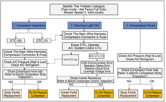
Troubleshooting
READ NEXT:
 Condenser
Condenser Components and components location
Condenser
Condenser Repair procedures
Inspection
Check the condenser fins for clogging and damage. Clean and blow
compressed air on any clogged fins. Unfold any bent fins
with a
A/C Pressure Transducer
A/C Pressure Transducer Components and components location
A/C Pressure Transducer
Description
A/C pressure transducer measures the pressure in high pressure line and
converts it into voltage. Based
on the converted voltage, engine ECU
Evaporator Core Repair procedures, Evaporator Temperature Sensor
Replacement
Disconnect the negative (-) battery terminal.
Remove the heater and blower assembly.
(Refer to Heater - "Heater Unit")
Remove the heater unit lower case (A) after loosening the mounting screws.
SEE MORE:
Front Washer Motor Repair procedures
Inspection
With the washer motor connected to the reservoir tank, fill the
reservoir tank with water.
Warning
Before filling the reservoir tank with water, check the filter for
foreign material or
contamination. if necessary, clean the
Lane Keeping Assist (LKA)
Lane Keeping Assist is designed to help
detect lane markings (or road edges)
while driving over a certain speed. Lane
Keeping Assist will warn the driver if the
vehicle leaves the lane without using the
turn signal, or will automatically ass
Categories
- Home
- KIA Niro EV, Hybrid - Second generation - (SG2) (2021-2024) - Owner's manual
- Kia Niro - First generation - (DE) (2017-2022) - Service and Repair Manual
- Contact Us