KIA Niro: Heater Core Repair procedures | Positive Temperature Coefficient (The PTC)
Replacement
- Disconnect the negative (-) battery terminal.
- Remove the heater and blower assembly.
(Refer to Heater -"Heater Unit")
- Loosen the mounting screws and remove heater core cover (A).
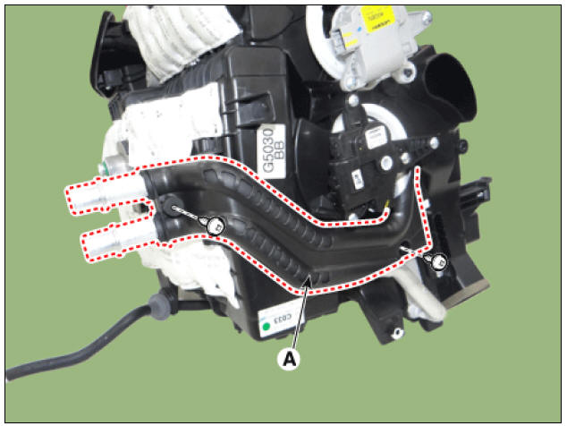
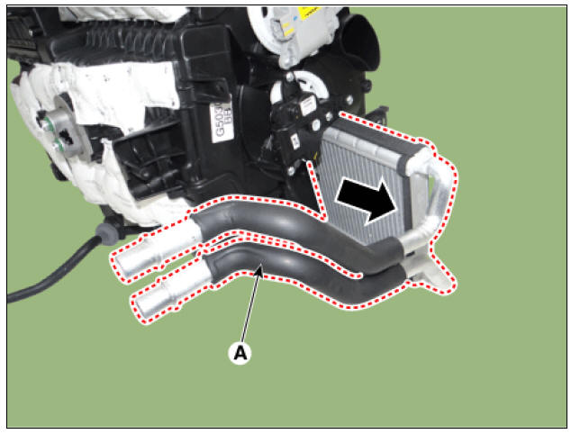
- Pull out the heater core (A) from the heater unit.
- Install in the reverse order of removal.
- When installing a new heater core, add refrigerant oil (POE OIL).
- Replace the O-rings with new ones at each fitting, and apply a thin coat of refrigerant oil before installing them. Be sure to use the right O-rings for R-134a, R-1234yf to avoid leakage.
- Immediately after using the oil, replace the cap on the container, and seal it to avoid moisture absorption.
- Do not spill the refrigerant oil on the vehicle; it may damage the paint; if the refrigerant oil contacts the paint, wash it off immediately.
- Apply sealant to the grommets.
- Make sure that there is no air leakage.
- Charge the system and test its performance.
- Install the hose clamps securely without interchanging the inlet and outlet heater hoses.
Positive Temperature Coefficient (The PTC)
Description
The PTC (Positive Temperature Coefficient) heater is installed at the exit or the backside of heater core.
The PTC heater is an electric heater using a PTC element as an auxiliary heating device that supplements deficiency of interior heat source in highly effective diesel engine. The electric heater heats up the interior by directly heating the air that passes through the heater. The name itself implies that the element has a proportional resistance change sensitive to temperature.
Operation Principle
ECM outputs a PTC ON signal and operates PTC relay 1. Then heater controller operates PTC relay 2 and PTC relay 3 with an interval of 15 seconds.
However, PTC relay 3 can be operated while battery voltage is above 12.4V.
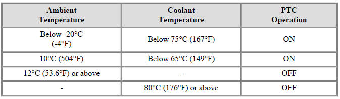
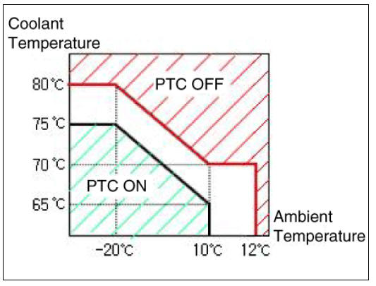
Operating Condition
PTC heater operates according to the following conditions;
- Battery voltage: 12.4V or above
- Engine : Running
- Ambient temperature and coolant temperature
Inspection
Operating Logic Test (Manual only)
Inspect the PTC operation by confirmation logic as follows;
- Entering
(1) Set the Floor mode and maximum heating position.
(2) Turn off the blower switch.
(3) Press the intake(recirculation) button 5 times or more.
(4) \Indicators of intake and A/C button are continuously flashed with an interval of 0.5 seconds.
(5) Confirm the PTC operation by turn on the blower switch.
(6) Each PTC relay is operated with an interval of 3 seconds.
(7) The logic test will be automatically cancelled after 30 seconds.
In addition, it can be cancelled by followings;
- Select A/C or intake (recirculation) switch
- Ignition switch OFF
- Cancellation
- Select A/C or intake (recirculation) switch.
- Turn the ignition switch OFF.
- The test is cancelled automatically after 30 seconds.
- If the PTC is not operated, substitute with a known-good PTC heater and check for proper operation.
If the problem is corrected, replace the PTC heater.
Operating Test
This test should be performed in the PTC ON conditions.
- Run the engine.
- Check the current on wiring with a clamp multi tester.
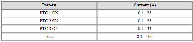
- If the current is not specification, inspect related wiring.
Resistance Test
- Turn the ignition switch OFF.
- Disconnect the PTC heater connector.
- Measure the resistance between terminal 1, 2, 3 of PTC heater and ground line.
Resistance : 0.3 - 1.5 �©
1) PTC 1
2) PTC 2
3) PTC 3
- If the measured resistance is not specification, replace the PTC heater with new one.
Replacement
- Disconnect the negative (-) battery terminal.
- Remove the crash pad lower panel.
(Refer to Body - "Crash Pad Lower Panel")
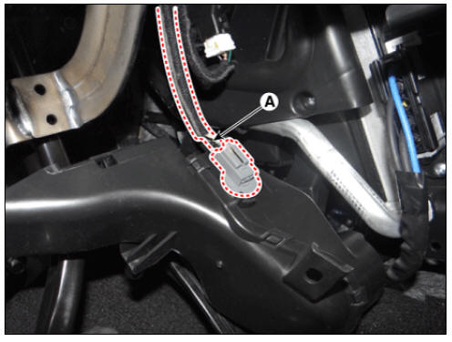
- Loosen the mounting screw and remove the driver shower duct (A).
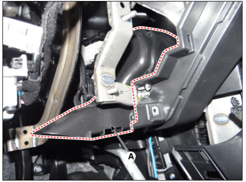
- Disconnect the duct sensor connector (A).
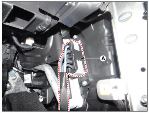
- Disconnect the PTC heater connector (A).
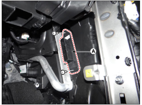
- Remove the PTC heater core (A) after loosening the mounting screws.
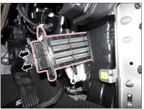
- Install in thje reverse order of removal.
READ NEXT:
 Temperature Control Actuator
Temperature Control Actuator Components and
components location
Temperature control actuator (LH)
Temperature control actuator (RH)
Description
Located in the heater unit, the temperature control actuator regulates the
temperature i
Mode Control Actuator Repair procedures
Mode Control Actuator Components and components location
Mode control actuator (LH)
Mode control actuator (RH)
Description
Located in the heater unit, the mode control actuator adjusts the position of
the mode door by
operating the m
SEE MORE:
Description of the ecall in-vehicle system
Road accident
Wireless network
Public Safety Answering Point (PSAP)
Rescue
The car is equipped with a device*1 connected
with the Pan-European eCall system
for making emergency call to
response teams. The Pan- European
eCall syste
Hybrid Control System / Description And Operation
The Hybrid Electric Vehicle (HEV) uses hybrid power source (Engine, Electric
motor), so its fuel efficiency is relatively
high and exhaust emission is very small compared to the traditional vehicle
which uses only engine as power source. It
con
Categories
- Home
- KIA Niro EV, Hybrid - Second generation - (SG2) (2021-2024) - Owner's manual
- Kia Niro - First generation - (DE) (2017-2022) - Service and Repair Manual
- Contact Us