KIA Niro: Front Strut Assembly Repair procedures
Removal
- Remove the wheel and tire.
Tightening torque: 107.9 - 127.5 N*m (11.0 - 13.0 kgf*m, 79.6 - 94.0 lb*ft)

Warning
Be careful not to damage the wheel nuts when removing the wheel and tire.
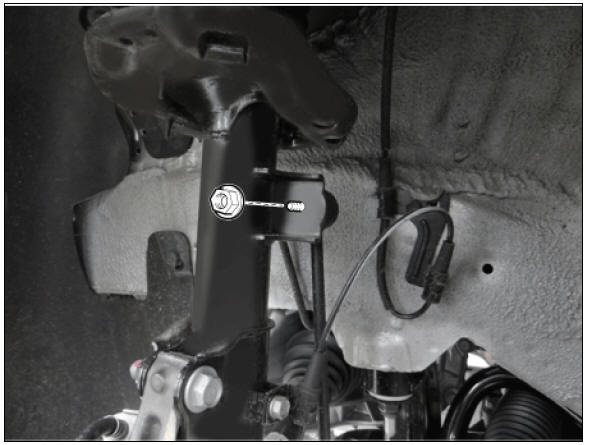
- Remove the stabilizer link nut.
Tightening torque: 98.0 - 117.6 N*m (10.0 - 12.0 kgf*m, 72.3 - 86.7 lb*ft)
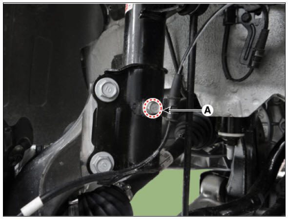
- Remove the wheel speed sensor bracket bolt (A).
Tightening torque: 8.8 - 13.7 N*m (0.9 - 1.4 kgf*m, 6.5 - 10.1 lb*ft)
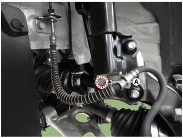
- Remove the caliper hose bracket bolt (A).
Tightening torque: 8.8 - 13.7 N*m (0.9 - 1.4 kgf*m, 6.5 - 10.1 lb*ft)
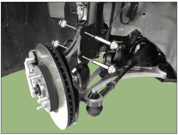
- Loosen the front strut lower bolts.
Tightening torque: 156.9 - 176.5 N*m (16.0 - 18.0 kgf*m, 115.7 - 130.2 Ib*ft)
- Remove the cowl top cover.
(Refer to Body - "Cowl Top Cover")
- Loosen the front strut upper nuts and then remove the strut assembly.
Tightening torque: 53.9 - 73.5 N*m (5.5 - 7.5 kgf*m, 39.8 - 54.2 Ib*ft)

Disassembly
- Using a strut spring compressor, compress the coil spring.

Warning
- To prevent peeling the paint of coil spring, cover the coil spring with a thin cloth or hose before installing strut spring compressor.
- Set the compression position of strut spring compressor correctly for coil spring not to slant when compressing the coil spring.
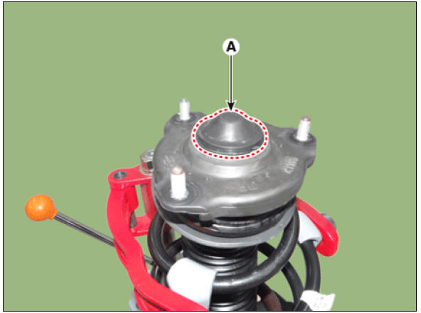
- Remove the insulator cap (A).
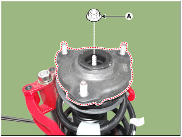
- Loosen the insulator nut (A) and then remove the insulator.
Tightening torque: 78.5 - 88.2 N*m (8.0 - 9.0 kgf*m, 57.9 - 65.0 lb*ft)
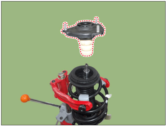
- Remove the strut bearing, spring upper pad and ruber.
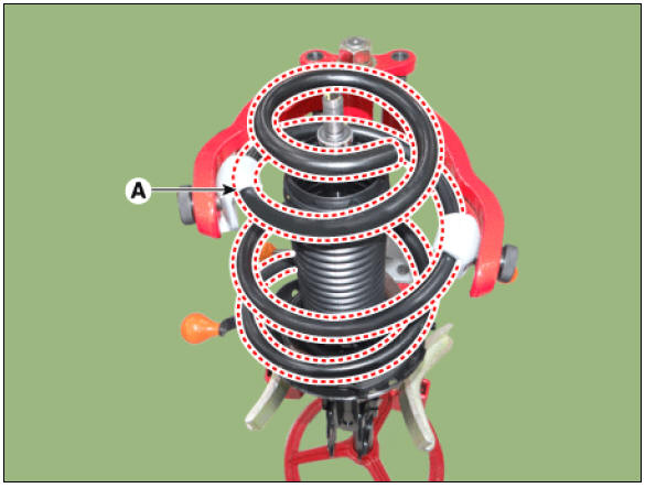
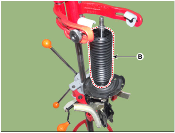
- Remove the spring (A) and dust cover (B).
- Remove the spring lower pad (A).

Inspection
- Check the strut insulator for wear or damage.
- Check rubber parts for damage or deterioration.
- Compress and extend the piston rod (A) and check that there is no abnormal resistance or unusual sound during operation.

Disposal
- Fully extend the piston rod.
- Drill a hole on the A section to remove gas from the cylinder.

Reassembly
- Install the spring lower pad (D) so that the protrusions (A) fits in the holes (C) in the spring lower seat (B).
- Compress coil spring using a strut spring compressor. Install compressed coil spring (A) into shock absorber.
Notice
- Identification color marks are indicated on the coil spring. Pay attention to identification mark during installation.
- Install the coil spring with the identification mark directed toward
the knuckle.
- After fully extending the piston rod, install the spring upper seat and insulator assembly.
- After seating the upper and lower ends of the coil spring (A) in the upper and lower spring seat grooves (B) correctly, tighten new self-locking nut temporarily
- Remove the special tool (09546-26000).
- Tighten the self-locking nut to the specified torque.
Tightening torque : 58.8 - 68.6 N*m (6.0 - 7.0 kgf*m, 43.4 - 50.6 lb*ft)
READ NEXT:
 Front Lower Arm Repair procedures
Front Lower Arm Components and components location
Components
Ball joint assembly
Front lower arm assembly
Front Lower Arm Repair procedures
Removal
Remove the wheel and tire.
Tightening torque:
107.9 - 127.5 N*m (11.0 - 13.0 k
Front Stabilizer Bar
Front Stabilizer Bar Components and components location
Stabilizer bar
Stabilizer link
Front Stabilizer Bar Repair procedures
Removal
Disconnect the battery negative cable.
Remove the universal bolt (A).
Tightening torque :
32
Sub Frame Repair procedures
Removal
Disconnect the battery negative cable.
Remove the universal bolt (A).
Tightening torque :
32.4 - 37.3 N*m (3.3 - 3.8 kgf*m, 23.9 - 27.5 lb*ft)
Warning
Keep neutral range to prevent damaging the clock spring inner
cable w
SEE MORE:
Wipers (Kia NIRO Hybrid)
Controlling wipers
Type A
Type B
Type C
Operation
Front wiper speed control
MIST/1x: Single wipe
/
: Off
INT/ *: Intermittent
control
wipe/Auto control wipe
LO/1: Low wiper speed
HI/2: High wiper speed
Wash w
Rear / Front Inlet Cooling Duct
Removal
Warning
Be sure to read and follow the "General Safety Information and Caution" before doing any work related with the high voltage system. Failure to follow the safety instructions may result in serious electrical inj
Categories
- Home
- KIA Niro EV, Hybrid - Second generation - (SG2) (2021-2024) - Owner's manual
- Kia Niro - First generation - (DE) (2017-2022) - Service and Repair Manual
- Contact Us