KIA Niro: Front Lower Arm Repair procedures
Kia Niro - First generation - (DE) (2017-2022) - Service and Repair Manual / Suspension System / Front Suspension System / Front Lower Arm Repair procedures
Front Lower Arm Components and components location
Components
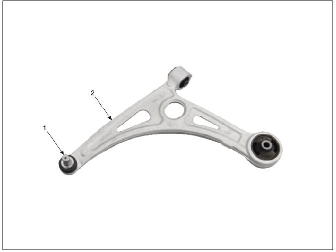
- Ball joint assembly
- Front lower arm assembly
Front Lower Arm Repair procedures
Removal
- Remove the wheel and tire.
Tightening torque: 107.9 - 127.5 N*m (11.0 - 13.0 kgf*m, 79.6 - 94.0 lb*ft)

Warning
Be careful not to damage the wheel nuts when removing the wheel and tire.
- Remove the under cover.
(Refer to Engine Mechanical System - "Engine Room Under Cover")
- Disconnect the lower arm from the knuckle by using the SST
(09568-1S100).
(1) Remove the lower arm pin (A) and nut (B).
Tightening torque : 78.5 - 98.1 N*m (8.0 - 10.0 kgf*m, 57.9 - 72.3 lb*ft)

(2) Disconnect the lower arm from the knuckle by using the SST (09568-1S100).

Warning
- When using SST, be sure not to damage the dust cover of lower arm ball joint.
- Keep SST tied to the car because there is a risk of injury by dropping the SST during removing the lower arm ball joint.
- The peripheral parts may be damaged when removing the lower arm ball joint with a general tool such as lever, so be sure to use SST.
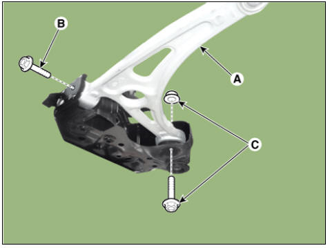
- Remove the lower arm (A) from the sub frame.
Tightening torque: B : 117.7 - 137.3 N*m (12.0 - 14.0 kgf*m, 86.8 - 101.3 lb*ft) C : 156.9 - 176.5 N*m (16.0 - 18.0 kgf*m, 115.7 - 130.2 lb*ft)
- Install in the reverse order of removal.
- Check the wheel alignment.
(Refer to Tires/Wheels - "Alignment")
Inspection
- Check the bushing for wear and deterioration.
- Check the lower arm for bending or breakage.
- Check the lower arm for deformation.
- Check all bolts and nuts.
READ NEXT:
 Front Stabilizer Bar
Front Stabilizer Bar Components and components location
Stabilizer bar
Stabilizer link
Front Stabilizer Bar Repair procedures
Removal
Disconnect the battery negative cable.
Remove the universal bolt (A).
Tightening torque :
32
Sub Frame Repair procedures
Removal
Disconnect the battery negative cable.
Remove the universal bolt (A).
Tightening torque :
32.4 - 37.3 N*m (3.3 - 3.8 kgf*m, 23.9 - 27.5 lb*ft)
Warning
Keep neutral range to prevent damaging the clock spring inner
cable w
SEE MORE:
Heating, Ventilation And Air Conditioning / Troubleshooting
Problem Symptoms Table
Before replacing or repairing air conditioning components, first determine if
the malfunction is due to
the refrigerant charge, air flow or compressor.
Use the table below to find the cause of the problem. The numbers in
Charging and climate
A: Electric Vehicle
Scheduled charging and target
temperature
Select EV ? Scheduled charging and
target temperature on the screen.
NOTICE
Vehicle must be connected with the
charging connector at the time prescheduled
time for the sc
Categories
- Home
- KIA Niro EV, Hybrid - Second generation - (SG2) (2021-2024) - Owner's manual
- Kia Niro - First generation - (DE) (2017-2022) - Service and Repair Manual
- Contact Us