KIA Niro: Exhaust Emission Control System
Description
Exhaust emissions (CO, HC, NOx) are controlled by a combination of engine
modifications and the
addition of special control components.
Modifications to the combustion chamber, intake manifold, camshaft and ignition
system form the
basic control system.
These items have been integrated into a highly effective system which controls
exhaust emissions
while maintaining good drivability and fuel economy.
Description
The catalytic converter of the gasoline engine is a three way catalyst. It oxidizes carbon monoxide and hydrocarbons (HC), and separates oxygen from the oxides of nitrogen (NOx).
Catalytic Converter (WCC)

CVVT (Continuous Variable Valve Timing) System Description and operation
Description
Continuous Variable Valve Timing (CVVT) system advances or retards the valve timing of the intake and exhaust valve in accordance with the ECM control signal which is calculated by the engine speed and load.
By controlling CVVT, the valve overlap or underlap occurs, which makes better fuel economy, reduces exhaust gases (NOx, HC) and improves engine performance by reducing pumping loss, giving internal EGR effect, improving combustion stability and volumetric efficiency, and increasing expansion work.
This system consists of
- the CVVT Oil Control Valve (OCV) which supplies the engine oil to the
cam phaser or takes out the engine oil from the cam phaser in accordance
with the ECM
PWM (Pulse Width Modulation) control signal, - the CVVT Oil Temperature Sensor (OTS) which measures the engine oil temperature,
- Cam Phaser : Changes the cam phase by using the hydraulic force of the engine oil.
The engine oil which is supplied from the CVVT oil control valve changes the cam phase in the direction (Intake Advance/Exhaust Retard) or opposite direction (Intake Retard/Exhaust Advance) of the engine rotation by rotating the rotor connected with the camshaft inside the cam phaser.

Intermediate Lock CVVT
It increases the retarded amount compared to the default state to expand the operating range of the variable valve timing system.
The cam phase is fixed mechanically so that it is locked at the middle
position.


Operation
Principle
The CVVT has the mechanism of rotating the rotor vane with hydraulic force
generated by the engine oil supplied to the advance or retard chamber in
accordance with
the CVVT oil control valve control.
Warning
- The variable force solenoid (VFS) changes its force depending on the PWM duty to control the stroke of the OCV.
- It also controls the lock, unlock, advanced, retarded, and holding functions.
- Intake CVVT

- Exhaust CVVT
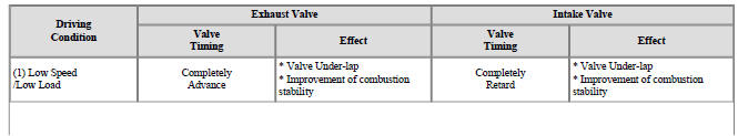
CVVT System Mode
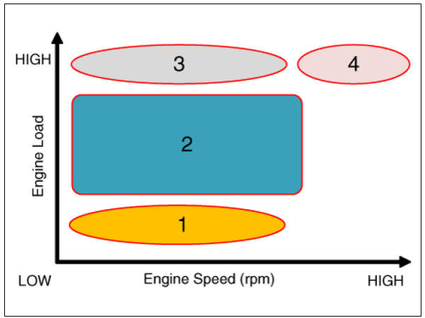
 Low Speed / Low Load
 Partial Load
 Low Speed / High Load
 High Speed / High Load

Circuit Diagram
Diagram Variable Force Solenoind (VFS) (Bank 1 / Intake)

Harness Connector

CVVT Oil Control Valve (OCV) (Bank 1 / Exhaust)

Harness Connector

Inspection
CVVT Oil Control Valve (OCV)
Refer to Engine Control / Fuel System - "CVVT Oil Control Valve (OCV)"
Removal
Variable Force Solenoind (VFS)
Refer to Engine Control / Fuel System - "Variable Force Solenoind (VFS)"
CVVT Oil Control Valve (OCV)
Refer to Engine Control / Fuel System - "CVVT Oil Control Valve (OCV)"
Installation
Variable Force Solenoind (VFS)
Refer to Engine Control / Fuel System - "Variable Force Solenoind (VFS)"
CVVT Oil Control Valve (OCV)
Refer to Engine Control / Fuel System - "CVVT Oil Control Valve (OCV)"
READ NEXT:
 The Gasoline Particulate Filter (GPF)
Description
The Gasoline Particulate Filter (GPF) system prevents Particulate Matter (PM)
from being discharged to the atmosphere and
consists of a filter assembly, two Exhaust Gas Temperature Sensors (EGTS). The
filter is integrated in the cat
Engine Control / Fuel System
Specifications
Fuel Delivery System
Sensors
Manifold Absolute Pressure Sensor (MAPS)
Type: Piezo-resistive pressure sensor type
Specification
Intake Air Temperature Sensor (IATS)
Type: Thermistor type
Specification
Basic Troubleshooting
Basic Troubleshooting Guide
Customer Problem Analysis Sheet
Basic Inspection Procedure
Measuring Condition of Electronic Parts' Resistance
The measured resistance at high temperature after vehicle
running may be high or low. So all
SEE MORE:
High Pressure Fuel Pump Repair procedures
Warning
In case of removing the high pressure fuel pump, high pressure fuel
pipe, delivery pipe, and injector, there may be injury
caused by leakage of the high pressure fuel. So don't do any repair work right
after engine stops.
Release th
Tire specification and pressure label
Type A
Type B
The tire label located on the center pillar
as shown gives the tire pressures recommended
for your vehicle. The tires supplied
on your new vehicle are chosen to
provide the best performance for normal
driving.
Motor number (
Categories
- Home
- KIA Niro EV, Hybrid - Second generation - (SG2) (2021-2024) - Owner's manual
- Kia Niro - First generation - (DE) (2017-2022) - Service and Repair Manual
- Contact Us