KIA Niro: CVVT & Camshaft Description and operation
Description
Continuous Variable Valve Timing (CVVT) system advances or retards the valve timing of the intake and exhaust valve in accordance with the ECM control signal which is calculated by the engine speed and load.
By controlling CVVT, the valve over-lap or under-lap occurs, which makes better fuel economy, reduces exhaust gases (NOx, HC) and improves engine performance through reduction of pumping loss, internal EGR effect, improvement of combustion stability, improvement of volumetric efficiency, and increased expansion work.
This system consists of
- the CVVT Oil Control Valve (OCV) which supplies the engine oil to the
cam phaser or runs out the engine oil from the cam phaser in accordance with
the ECM
PWM (Pulse With Modulation) control signal, - the CVVT Oil Temperature Sensor (OTS) which measures the engine oil temperature,
- and the Cam Phaser which varies the cam phase by using the hydraulic force of the engine oil.
The engine oil released from the CVVT oil control valve varies the cam phase
in the direction (Intake Advance/Exhaust Retard) or opposite direction (Intake
Retard/
Exhaust Advance) of the engine rotation by rotating the rotor connected with the
camshaft inside the cam phaser.

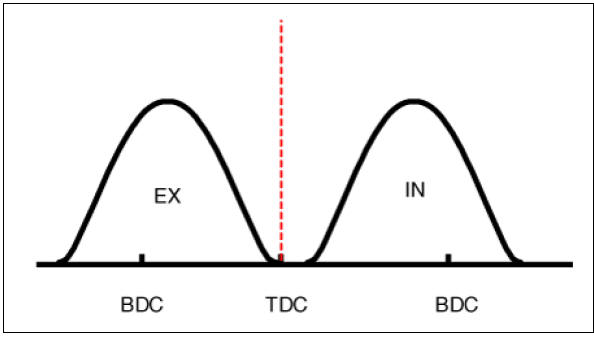
Operation Principle
The CVVT has the mechanism of rotating the rotor vane with hydraulic force
generated by the engine oil supplied to the advance or retard chamber in
accordance with
the CVVT oil control valve control.
- Intake CVVT

- Exhaust CVVT
CVVT System Mode
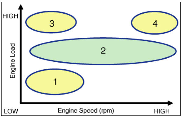
- Low Speed / Low Load

- Partial Load

- Low Speed / High Load

- High Speed / High Load

READ NEXT:
 CVVT & Camshaft Repair procedures
Removal
Warning
Use fender covers to avoid damaging painted surfaces.
To avoid damaging the cylinder head, wait until the engine
coolant temperature drops below normal
temperature (20ºC (68ºF)) before removing it.
When handling a meta
Cylinder Head Repair procedures
Removal
Engine removal is not required for this procedure.
Warning
Be sure to read and follow the "General Safety Information and
Caution" before doing any work related
with the high voltage system. Failure to follow the safety instruction
Cylinder Head
Inspect for flatness.
Using a precision straight edge and feeler gauge, measure the contacting
surface of the cylinder block and check
the manifolds for warpage.
If the flatness is greater than maximum, replace the cylinder head.
Fla
SEE MORE:
Tailgate Assembly
Tailgate / Repair Procedures
Adjustment
After loosening the tailgate hinge (A) mounting
bolts, adjust the tailgate by moving it up and down, or right and left.
Adjust the tailgate height by turning the tailgate
overslam bumpers (B).
Af
Memory Power Seat Switch
Connector and Terminal Function
Memory power seat switch Repair procedures
Removal
Disconnect the negative (-) battery terminal.
Remove the driver front door trim.
(Refer to Body - "Front Door Trim")
Remove the memory power
Categories
- Home
- KIA Niro EV, Hybrid - Second generation - (SG2) (2021-2024) - Owner's manual
- Kia Niro - First generation - (DE) (2017-2022) - Service and Repair Manual
- Contact Us