KIA Niro: Cooling Fan Repair procedures
Installation
Warning
- Be sure to read and follow the "General Safety Information and
Caution" before doing any work related with the high voltage system. Failure
to follow the safety
instructions may result in serious electrical injuries. - Be sure to read and follow the "High Voltage Shut-off Procedures" before doing any work related with the high voltage system. Failure to follow the safety instructions may result in serious electrical injuries.
- Install the cooling fan in the reverse order of removal.
Inspection
Warning
- Be sure to read and follow the "General Safety Information and
Caution" before doing any work related with the high voltage system. Failure
to follow the safety
instructions may result in serious electrical injuries. - Be sure to read and follow the "High Voltage Shut-off Procedures" before doing any work related with the high voltage system. Failure to follow the safety instructions may result in serious electrical injuries.
- Turn OFF the ignition switch and disconnect the (-) cable on the auxiliary battery (12V).
- Connect the KDS to the self-diagnosis connector (DLC).
- Turn ON the ignition switch.
- Use the KDS device to perform forced operation.
- Use a multimeter to ensure that the cooling fan is powered.
- Cooling fan B+ : cooling fan connector (4) pin
- Cooling fan ground : cooling fan connector (8) pin
- Check the fan motor speed in the GSD device service data.
Specification : Refer to "Specification"
Warning
When checking the power supply of the cooling fan, check measure using the of the cooling fan connector (A).
(Reason : Wire / fuse break, Purpose of preventing improper maintenance due to connector contact failure etc.)
 Cooling Fan #1
 Cooling Fan #2
Description
Plug-in hybrid vehicle can be normal charge.
In the case of normal charge, the battery is charged after 220V AC power is
transformed to DC power
by On-Board Charger (OBC).
While charging the vehicle, the driving of the vehicle is restricted.
Description
In normal charge, the battery is charged through the On-Board Charger (OBC)
using external power
supply of 220V.
On-Board Charger (OBC) is the equipment that charges the high voltage battery of
electric vehicle
using the 110 - 220V AC power.

Main Function

Removal
Warning
- Be sure to read and follow the "General Safety Information and Caution" before doing any work related with the high voltage system. Failure to follow the safety instructions may result in serious electrical injuries.
- Be sure to read and follow the "High Voltage Shut-off Procedures" before doing any work related with the high voltage system. Failure to follow the safety instructions may result in serious electrical injuries.
- Turn ignition switch OFF and disconnect the negative (-) battery cable.
- Shut off the high voltage circuit.
(Refer to Hybrid Control System - "High Voltage Shutoff Procedure")
- Drain the coolant by loosening the drain plug.
(Refer to Hybrid Motor System - "Coolant")
- Remove the LH front wheel & tire and wheel house cover.
- Remove the front bumper assembly.
(Refer to Body - "Front Bumper Cover")
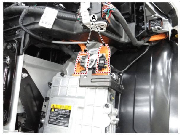
- Disconnect the OBC cable connector (A).
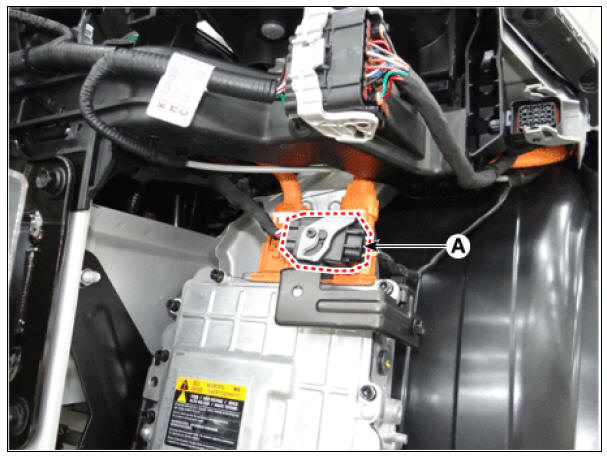
- Disconnect the OBC signal connector (B).
- Disconnect the OBC coolant hose (A) and coolant hose quick-connector.
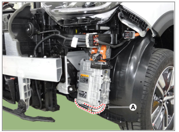
- Remove the OBC mounting bolt (A) and nut (B).
OBC mounting bolt / nut : 23.5 - 24.5 N*m (2.4 - 2.5 kgf*m, 17.3 - 18.1 lb*ft)
- Remove the OBC (C).

Installation
Warning
- Be sure to read and follow the "General Safety Information and Caution" before doing any work related with the high voltage system. Failure to follow the safety instructions may result in serious electrical injuries.
- Be sure to read and follow the "High Voltage Shut-off Procedures" before doing any work related with the high voltage system. Failure to follow the safety instructions may result in serious electrical injuries.
- Install the OBC in the reverse order of removal.
Warning
Refill the hybrid motor cooling system coolant and perform air bleeding by using the KDS.
(Refer to Hybrid Motor Cooling System - "Coolant")
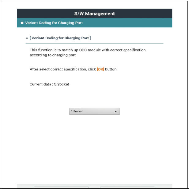
- After installing the on-board charger (OBC), perform the matching operation according to the regional (European, domestic / North American) charging port specifications.
(1) Turn the igntion switch OFF.
(2) Connect the KDS to Data Link Connector (DLC).
(3) Select "Vehicle, Model year, Engine, System".
(4) Select "Vehicle S/W Management".
(5) Select "Variant Coding for Charging port".

(6) According to the KDS instructions to execute "Variant Coding for Charging port".
(7) According to the KDS instructions, select the regional specification. (Domestic / North America: 5 Socket, Europe: 7 Socket)

READ NEXT:
 Сharge port
Description
Location of normal charge port in the front fender of vehicle. The charge
starts when the ICCB or the
is connected to charge port.
Removal
Warning
Be sure to read and follow the "General Safety Information and
Ca
Low Voltage DC/DC Converter (LDC)
Component Location
Low Voltage DC/DC Converter (LDC) (HPCU)
Low Voltage DC/DC Converter (LDC) power output
terminal (+) (DC 12V)
Low Voltage DC/DC Converter (LDC) ground terminal (-)
Schematic Diagram
Low Voltage DC/DC Converter
SEE MORE:
Exterior overview
Front view
* The actual features in your vehicle may not necessarily be available due to
the
selected options or regions.
Hood
Head lamp
Wheel and tire
Outside rear view mirror
Sunroof
Front windshield wiper blades
Windows
F
Piston and Connecting Rod Repair procedures
Disassembly
Warning
Be sure to read and follow the "General Safety Information and
Caution" before doing any work related
with the high voltage system. Failure to follow the safety instructions may
result in serious electrical
injuries
Categories
- Home
- KIA Niro EV, Hybrid - Second generation - (SG2) (2021-2024) - Owner's manual
- Kia Niro - First generation - (DE) (2017-2022) - Service and Repair Manual
- Contact Us