KIA Niro: Cooling Fan Description and operation | Cooling Fan Repair procedures
Component
Location
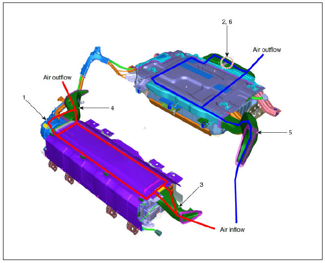
- Cooling Fan #1
- Cooling Fan #2
- Main High Voltage Battery Cooling Duct (Inlet)
- Main High Voltage Battery Cooling Duct (Outlet)
- Sub High Voltage Battery Cooling Duct (Inlet)
- Sub High Voltage Battery Cooling Duct (Outlet)
Specification
Current

Duty

Description
The cooling Fan consists of the main connector, the cooling fan relay and the BLDC motor. It is
controlled by the BMS ECU PWM signal which varies with the high voltage battery condition (9-
Speed).
Cooling Fan
Cooling Fan #1
Components
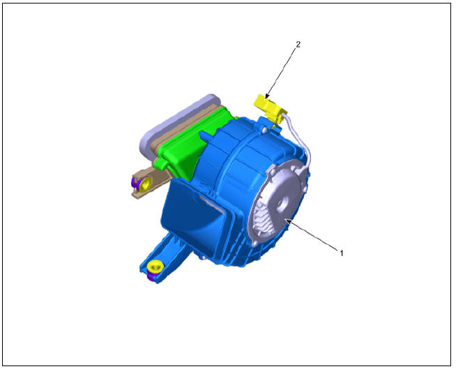
- BLDC Motor
- Main Connector
Cooling Fan #2
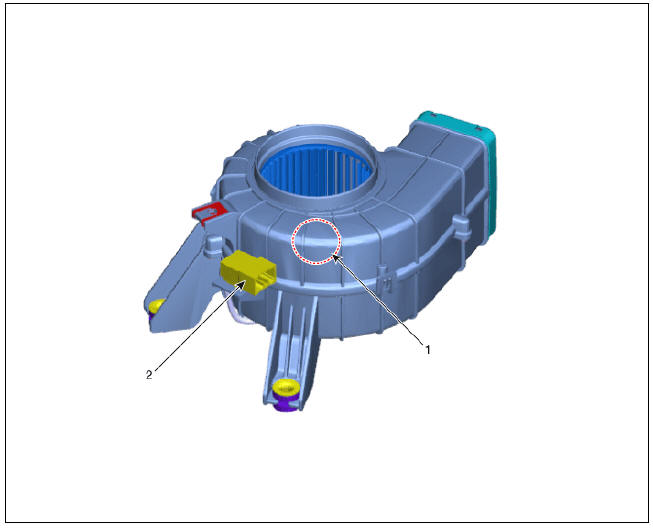

- BLDC Motor
- Main Connector
Cooling Fan Repair procedures
Removal
Warning
- Be sure to read and follow the "General Safety Information and Caution" before doing any work related with the high voltage system. Failure to follow the safety
instructions may result in serious electrical injuries. - Be sure to read and follow the "High Voltage Shut-off Procedures" before doing any work related with the high voltage system. Failure to follow the safety instructions may result in serious electrical injuries.
Cooling Fan #1 (High Voltage Main Battery)
- Shut off the high voltage circuit.
(Refer to Hybrid Control System - "High Voltage Shut-off Procedures")
- Remove the rear seat cushion.
(Refer to Body - "Rear Seat Assembly")
- Remove the rear door scuff trim.
(Refer to Body - "Door Scuff Trim")
- Remove the inlet cooling duct.
(Refer to High Voltage Battery Cooling System - "Cooling Duct")
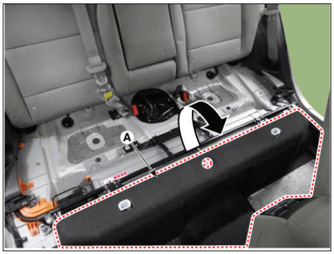
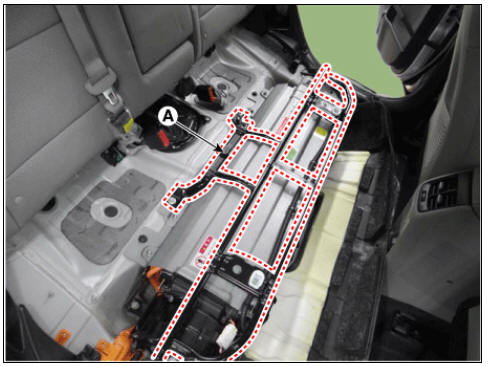
- Open the high voltage battery cushion (A) in the direction of an arrow.
- Remove the upper frame (A) after loosening the mounting bolts and nuts.
- Remove the outlet cooling duct.
(Remove the High Voltage Cooling System - "Cooling Duct")
- Disconnect the cooling fan connector (A).
- Remove the cooling fan after loosening the mounting bolts and nuts (B).

Cooling Fan #2 (High Voltage Sub Battery)
- Switch "OFF" the ignition and disconnect the negative (-) terminal of the auxiliary 12V battery.
- Shut off the high voltage circuit.
(Refer to Hybrid Control System - "High Voltage Shutoff Procedure")
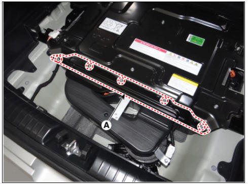
- Remove the high voltage rear cover (A) after loosening the mounting bolt.
High Voltage Battery Rear Cover mounting bolt : 7.8 - 11.8 N*m (0.8 - 1.2 kgf*m, 5.8 - 8.7 lb*ft)
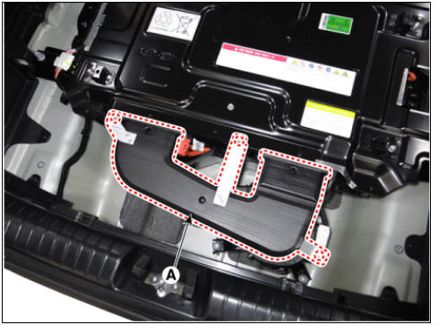
- Remove the rear outlet cooling duct (A) after loosening the mounting bolt.
Rear Outlet Cooling Duct mounting bolt : 7.8 - 11.8 N*m (0.8 - 1.2 kgf*m, 5.8 - 8.7 lb*ft)
- Remove the cooling fan connector (A).
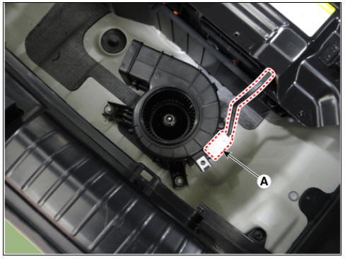
- Remove the cooling fan (B) after loosening the mounting bolts (A).

Installation
Warning
- Be sure to read and follow the "General Safety Information and Caution" before doing any work related with the high voltage system. Failure to follow the safety
instructions may result in serious electrical injuries. - Be sure to read and follow the "High Voltage Shut-off Procedures" before doing any work related with the high voltage system. Failure to follow the safety instructions may result in serious electrical injuries.
- Install the cooling fan in the reverse order of removal.
Inspection
Warning
- Be sure to read and follow the "General Safety Information and Caution" before doing any work related with the high voltage system. Failure to follow the safety
instructions may result in serious electrical injuries. - Be sure to read and follow the "High Voltage Shut-off Procedures" before doing any work related with the high voltage system. Failure to follow the safety instructions may result in serious electrical injuries.
- Turn OFF the ignition switch and disconnect the (-) cable on the auxiliary battery (12V).
- Connect the KDS to the self-diagnosis connector (DLC).
- Turn ON the ignition switch.
- Use the KDS device to perform forced operation.
- Use a multimeter to ensure that the cooling fan is powered.
- Cooling fan B+ : cooling fan connector (4) pin
- Cooling fan ground : cooling fan connector (8) pin
- Check the fan motor speed in the GSD device service data.
Specification : Refer to "Specification"
Warning
- When checking the power supply of the cooling fan, check measure using the of the cooling fan connector (A).
(Reason : Wire / fuse break, Purpose of preventing improper maintenance due to connector contact failure etc.)
Cooling Fan #1

Cooling Fan #2

READ NEXT:
 Rear / Front Inlet Cooling Duct
Removal
Warning
Be sure to read and follow the "General Safety Information and Caution" before doing any work related with the high voltage system. Failure to follow the safety instructions may result in serious electrical inj
SEE MORE:
Vehicle parasitic current inspection
Using the Ammeter
Turn the all electric devices OFF, and then turn the ignition switch OFF.
Close all doors except the tailgate, and then lock all doors.
Disconnect the tailgate latch connector.
Wait a few minutes until the vehicle's electr
License Lamps Repair procedures | High Mounted Stop Lamp Repair procedures
Removal
Disconnect the negative (-) battery terminal.
Remove the license lamp assembly (A) after pressing the locking pin.
Disconnect the license lamp connector (A).
Remove the license lamp bulb (B) after removing th
Categories
- Home
- KIA Niro EV, Hybrid - Second generation - (SG2) (2021-2024) - Owner's manual
- Kia Niro - First generation - (DE) (2017-2022) - Service and Repair Manual
- Contact Us