KIA Niro: Clutch Engagement Fork and Engagement Bearin
Kia Niro - First generation - (DE) (2017-2022) - Service and Repair Manual / DCT(Dual Clutch Transmission) System / Dual Clutch System / Clutch Engagement Fork and Engagement Bearin
Components
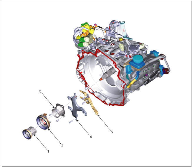
- Engagement bearing 2 (Even)
- Engagement bearing 1 (Odd)
- Engagement bearing sleeve
- Engagement fork 1 (Odd)
- Engagement fork 2 (Even)
Clutch Engagement Fork and Engagement Bearing Repair procedures
Removal
- Remove the dual clutch assembly.
(Refer to Double Clutch System - "Double Clutch Assembly")
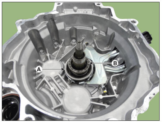
- Remove the clutch engagement bearing 1 (A) and 2 (B).
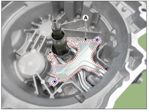
- Remove the clutch engagement fork 1 (A).
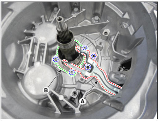
- Remove the clutch engagement fork 2 (A) and engagement bearing sleeve (B).
Installation
Warning
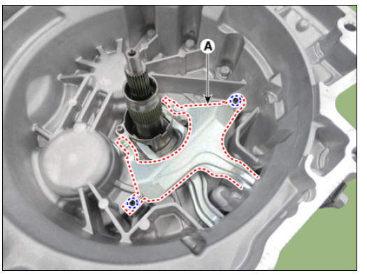
Check the assembled state of the knock bush (A) and dowel pins (B).

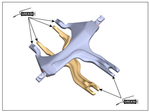
- Apply the grease on end part of fork.
Specified grease : Extreme pressure grease for vehicle
Quantity : 0.1 - 0.2 g
- Install the clutch engagement fork 2 (A) and the bearing sleeve (B) together.
Tightening torque : 9.8 - 11.8 N*m (1.0 - 1.2 kgf*m, 7.2 - 8.7 lb*ft)

Warning
- Precisely install the shaft clutch engagement fork to the dowel pin.
- Pretighten each bolt, and then fully tighten the bolts to the specified torque.
- Install the engagement fork 1 (A).
Tightening torque : 9.8 - 11.8 N*m (1.0 - 1.2 kgf*m, 7.2 - 8.7 lb*ft)
- Install the engagement bearing 1 (A).

Warning
Align the bearing plastic guide and the clutch engagement fork.
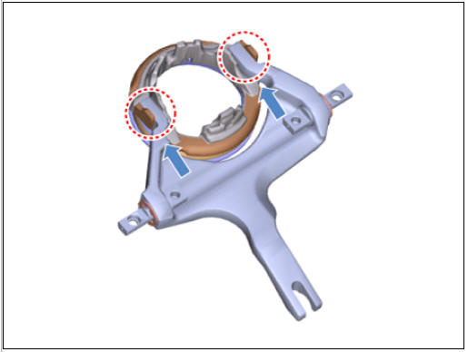
- Install the engagement bearing 2 (A).

Warning
Check that the bearing plastic stopper (B) is seated in the sleeve (C).
- Install the dual clutch assembly.
(Refer to Double Clutch System - "Double Clutch Assembly")
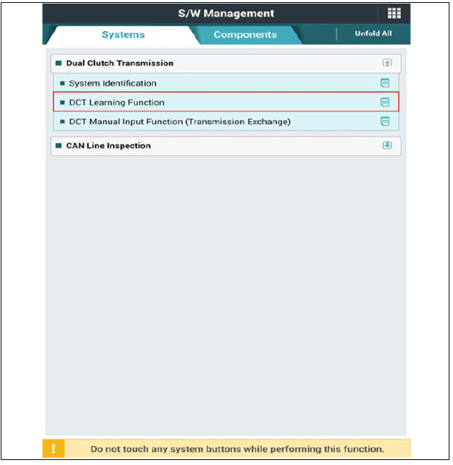
- Perform the clutch touch pointlearning procedure using the KDS.
READ NEXT:
 Hybrid Motor System
Specifications
Hybrid Drive Motor
Hybrid Starter Generator (HSG)
Electric Water Pump (EWP)
Coolant
Tightening Torques
Special Service Tools
Tool Name /
Number/
Illustration / Description
Pressure cap
pressure
checke
Hybrid Drive Motor Assembly Components and components location, Repair procedures
Component
location!
HPCU (Hybrid Power Control Unit) (LDC+MCU+HCU+Reservoir)
Hybrid drive motor
Hybrid starter generator (HSG)
Electrical radiator
Electric water pump (EWP)
Components
Hybrid motor assembly
SEE MORE:
Front Lower Arm Repair procedures
Front Lower Arm Components and components location
Components
Ball joint assembly
Front lower arm assembly
Front Lower Arm Repair procedures
Removal
Remove the wheel and tire.
Tightening torque:
107.9 - 127.5 N*m (11.0 - 13.0 k
Front Seat Back Cover
Front seat back cover
Replacement
Remove the front seat assembly.
(Refer to Front Seat - "Front Seat Assembly")
Remove the front seat outer shield cover.
(Refer to Front Seat - "Front Seat Outer Shield Cover")
Categories
- Home
- KIA Niro EV, Hybrid - Second generation - (SG2) (2021-2024) - Owner's manual
- Kia Niro - First generation - (DE) (2017-2022) - Service and Repair Manual
- Contact Us