KIA Niro: Battery Tester - The MDX-670P Analyzer
The MDX-670P battery conductance and electrical system analyzer tests batteries as well as starting and charging systems for vehicle.
It displays the test results in seconds and features a built-in printer to provide a copy of the results.

Warning
1) Because of the possibility of personal injury, always use extreme caution and appropriate eye protection when working with batteries.
2) When charging battery by test result, Battery must be fully
charged. To get accurate test result, battery
surface voltage must have subsided ahead before test when you test battery after
charged. (See following
Battery Test Results)
Warning
When testing the vehicle with old diesel engines, the test result will not be favorable if the glow plug is not heated. Conduct the test after warming up the engine for 5 minutes.
- Connect the red clamp to the positive (+) terminal and the black clamp to the negative (-) terminal.
Warning
For a proper connection, rock the clamps back and forth. The tester
requires that both sides of each clamp be
firmly connected before testing. A poor connection will produce a CHECK
CONNECTION or WIGGLE
CLAMPS message. If the message appears, clean the terminals and reconnect the
clamps.
- Scroll to and select IN VEHICLE or OUT OF VEHICLE for a battery not connected to a vehicle.

Warning
Following an IN VEHICLE test you will be prompted to test the starting and charging systems.
- Scroll to and select REGULAR FLOODED, AGM FLAT PLATE, or AGM SPIRAL where applicable.

Warning
If the vehicle equipped with ISG function, select the AGM FLAT PLATE.
- Scroll to and select the battery's rating system.
Warning
Mostly, the CCA value is marked on the battery label, but sometimes marked EN or SEA value. Select one of them.
- CCA: Cold Cranking Amps, as specified by SAE. The most common rating for cranking batteries at 0 ºF (- 17.8 ºC).
- EN: Europe-Norm
- SAE: Society of Automotive Engineers, the European labeling of CCA
- Set the selected rating value displayed on the screen to the value marked on the battery label by pressing up and down arrow buttons.
- Press ENTER to start test.
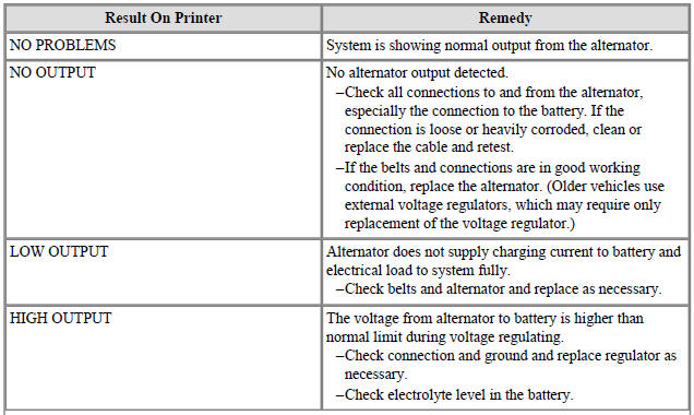
- After several seconds the tester displays the decision on the battery's condition and the measured voltage. The tester also displays your selected battery rating and the rating units.

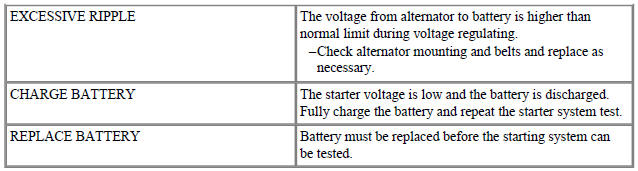
Battery Test Results
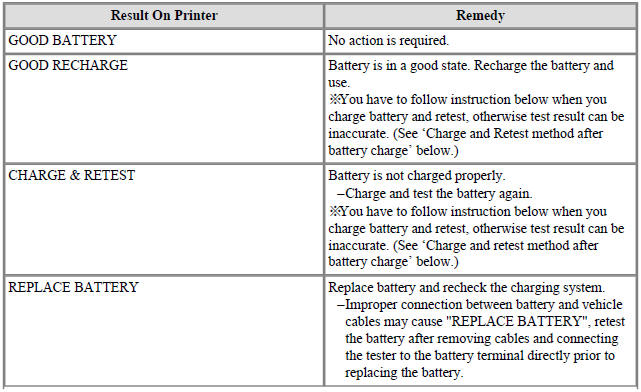

Charge and Retest method after battery charge
Battery charge
Set battery charger to 'Auto Mode' (The Mode that charging current drops as
the battery charges.) and charge
battery until charging current down close to zero or the charger alerts you with
an alarm when charge is
complete.(Minimum charging time recommended: More than 3 hours with Auto Mode
that explained above)
- If battery is not fully charged, battery surface voltage will be high while the amount of current charged (CCA) in battery is low. If you measure the battery under this condition, tester may misjudge that battery sulfation occurred because the amount of current in battery is too low in comparison with battery voltage.
Surface voltage: When battery is charged electrolyte temperature increases and chemical reaction become active resulting in an excessive increase of battery voltage.
It is known that it takes approximate one day to subside this increased surface voltage completely.
Battery Test after charge
Do not test battery right after the charge. Test battery after battery surface voltage has subsided as instructed in the following procedure.
(1) When battery charge is complete, install the battery in the vehicle.
(2) Put IG key to ON position and turn on head lamp with low beam, and wait 5 minutes. (Discharge for 5 minutes)
(3) Turn off the head lamp and IG key, and wait 5 minutes. (Waiting for 5 minutes)
(4) Remove +, - cable from the battery and test battery.
Warning
For an in-vehicle test, the display alternates between the test results and the message "PRESS FOR STARTER TEST.
Warning
Before starting the test, inspect the alternator drive belt. A belt that is glazed or worn, or lacks the proper tension, will prevent the en¬gine from achieving the rpm levels needed for the test.
- Press the ENTER button to proceed with the starter test.
- Start the engine when prompted.
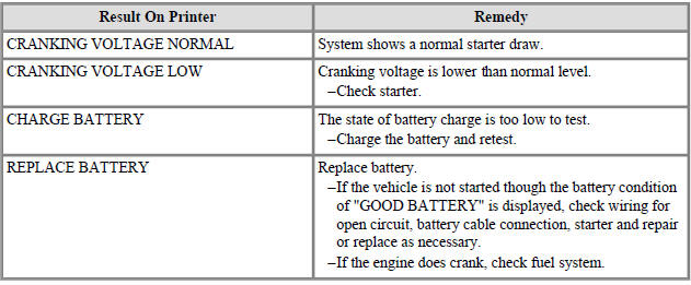
- The tester displays the decision on the starter system, cranking voltage, and cranking time in milliseconds.

Starter Test Results
Warning
For an in-vehicle test, the display alternates between the test results and the message "PRESS FOR CHARGING TEST.
Step 3: Charging System Test
- Press the ENTER button to proceed with the charging test.
- Rev the engine with loads off. (Following the on-screen prompts)

- The message that engine RPM is detected will be displayed on the screen, idle the engine.
- Turn on electrical loads (air conditioner, lamps, audio and etc). Press ENTER to continue.
- Turn on electrical loads (air conditioner, lamps, audio and etc). Press ENTER to continue.
- The message that engine RPM is detected will be displayed on the screen, idle the engine.
- Turn off loads and engine.
- The Charging System decision is displayed at the end of the procedure.
- Press the BACK/PRINT button to print the test results or MENU to return to the Options Menu.
Installation
- Install in the reverse order of removal.
Warning
When installing the battery, fix the mounting bracket on the tray correctly.
Warning
After disconnecting then reconnecting the battery negative cable, reset some parts that require the reset procedures.
(Refer to Body Electrical System - "General Information")
READ NEXT:
 Cleaning
Make sure the ignition switch and all accessories are in the OFF
position.
Remove the battery from the vehicle.
(Refer to Charging System - "Battery")
Warning
Care should be taken in the event the battery case is cracked or
Battery Sensor Repair procedures
Removal
Open the trunk.
Remove the luggage side trim (RH) side cover (A).
Turn the ignition switch OFF and disconnect the battery negative (-)
terminal (A).
Disconnect the battery sensor connector (B).
Battery (-) terminal tig
Ignition System
Description
Ignition timing is controlled by the electronic control ignition timing
system. The standard reference
ignition timing data for the engine operating conditions are preprogrammed in
the memory of the ECM
(Engine Control Module).
SEE MORE:
Rear Seat Cushion Cover | Rear Back Armrest
Rear seat cushion cover
Replacement
Remove the seat assembly.
(Refer to Rear Seat - "Rear Seat Assembly")
Remove the rear seat cushion cover (A) after removing the hog-ring clips on the rear of seat cushi
Seat belts
Seat belts are designed to bear upon the
bony structure of the body, and should
be worn low across the front of the pelvis,
chest and shoulders.
WARNING
For maximum restraint system protection,
the seat belts must always be
used whenever
Categories
- Home
- KIA Niro EV, Hybrid - Second generation - (SG2) (2021-2024) - Owner's manual
- Kia Niro - First generation - (DE) (2017-2022) - Service and Repair Manual
- Contact Us