KIA Niro: TJ Joint Repair procedures
Removal
Warning
- Drive shaft joints require special grease, so do not add any other type of grease.
- When replacing the boot band, it must be a new one.
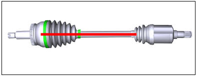
- Remove the front drive shaft.
(Refer to Driveshaft Assembly - "Front Driveshaft")
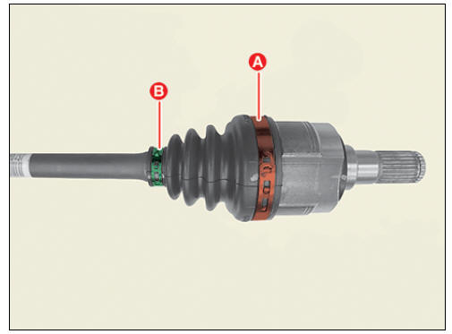
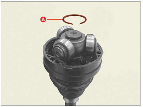
- Remove the transaxle side large diameter (A) and small diameter (B) boot bands.
Warning
Use the right tool for each type of boot band as shown in the table
below. 

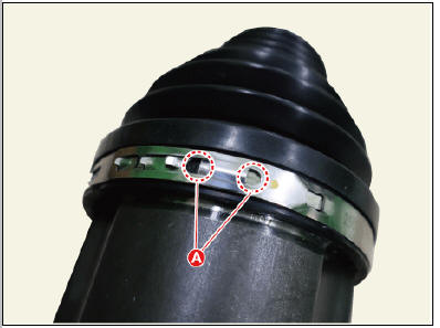
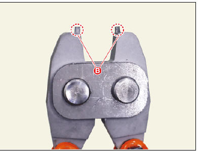
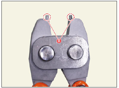
Warning
When using the low profile hook type boot band, fit the SST tip (B)
into the boot band hole (A) as shown below.
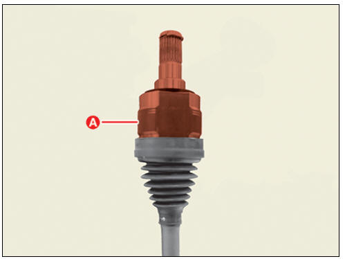
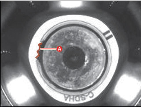
- Remove the trans axle joint housing (A).
- Remove the snap ring (A) using a snap ring pliers.
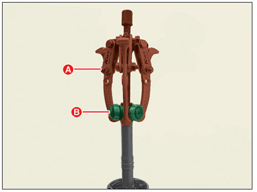
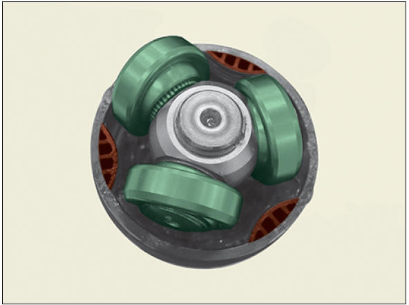
- Remove the spider assembly (B) from the drive shaft using a puller (A).
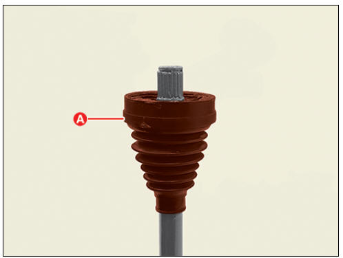
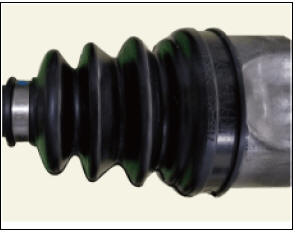
- Remove trans axle side boot (A).
- Clean the inside of the spider assembly and joint housing.
Warning
Remove grease inside the housing as much as possible.
Inspection
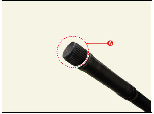
- Check spline (A) for damage / wear / crack.
- Check the boot for water or foreign objects.
- Check joint assembly for damage / wear / crack and rust.
- Replace any defective parts.
Installation
Warning
- When assembling, be careful not to let dust and foreign substances enter.
- Driveshaft joints require special grease, so do not add any other type of grease.
- Boot bands must use the new one.
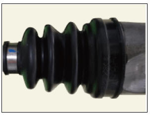
- Install the transaxle side boot (A) and boot band (B) on the driveshaft.

Warning
Put the boot band (B) first on the drive shaft before installing the boot (A).
- Install the spider assembly (A) on the shaft (B), then press it using a mallet.

Warning
 When installing
the spider assembly (A), install it in the correct direction.
When installing
the spider assembly (A), install it in the correct direction.- Installing in the wrong direction can cause secondary quality problems.
- Install the snap ring (A) using the snap ring pliers.

Warning
- When replacing the joint assembly, use the new one provided in the joint kit.
- The snap ring must be new.
- After installing the snap ring, make sure that there are only 2
- 3 splines in position (A).
- Install the transaxle side joint boot (A) in the correct position.

Warning
- When installing boot (A), make sure the boot fits into the
groove (B).

- When installing the spider assembly, fit the assembly to the
boot shape.
- Apply specified grease inside the joint housing (A) and boot (B).
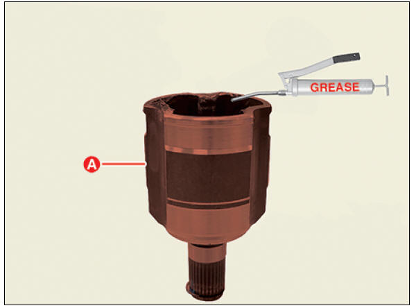

Warning
- Use the grease provided with the joint/boot kit.
- Apply about 70% grease to the housing (A) and about 30% grease to the boot (B).
- Driveshaft joints require special grease, so do not add any other type of grease.
- Install the trans axle side joint housing (A).

Warning
- When installing the housing, turn the boot to fit each other.
- If the shape of housing and boot does not fit, there is a possibility of leakage due to the gap. Be very careful.
- Adjust the air inside the boot to normal as shown below.
 Normal
 Lack of air
 Too much air
- Install the transaxle side joint large diameter (A) and small diameter (B) boot band.

Warning
Use the right tool for each type of boot band as shown in the table
below. 
Warning
- Install in the following order: large diameter boot band (A) Õ small diameter boot band (B).
- Installing in the wrong order can cause leaks.
- When installing the boot band, align the fastened direction
with the wheel side joint boot band.
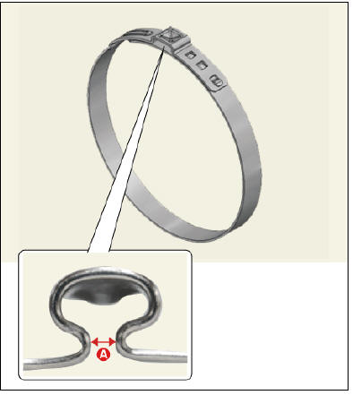
- When installing the ear type boot band, check the clearance (A) as shown below.
Clearance (A) : 2.0 mm or less.
- When using the low profile hook type boot band, fit the SST tip
(B) into the boot band hole (A) as shown below.

- Install the front drive shaft.
(Refer to Driveshaft Assembly - "Front Driveshaft")
TJ Joint Repair procedures
Removal
- Remove the front drive shaft.
(Refer to Driveshaft Assembly - "Front Driveshaft")
- Remove the trans axle side joint.
(Refer to Driveshaft Assembly - "Joint Assembly (Transaxle side)")
- Remove the dynamic damper band (A) using driver (-).
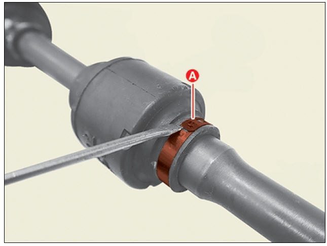
Warning
When removing the dynamic damper, lubricate the shaft with soapy
water to prevent shaft
damage.
- Remove the dynamic damper (A).

Installation
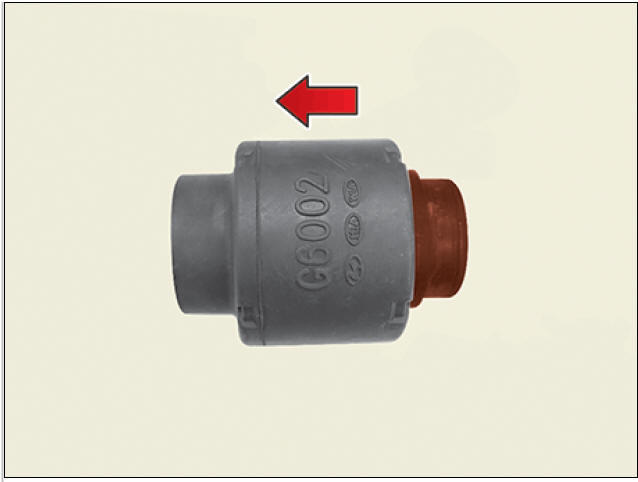
- Install the dynamic damper (A).

Warning
When installing the dynamic damper, install it in the direction of
the arrow. Installing in the
wrong direction can cause secondary quality problems.
- Install the dynamic damper band (A) using SST (09495-39100).

Warning
When installing the dynamic damper (A), make sure that the damper
fits into the groove (B). 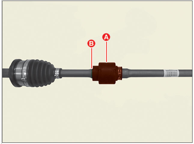
- Install the transaxle side joint.
(Refer to Driveshaft Assembly - "Joint Assembly(Transaxle side)")
- Install the front driveshaft.
(Refer to Driveshaft Assembly - "Front Driveshaft")
READ NEXT:
 Driveshaft Assembly
Removal
The type can replace the wheel side joint boot
Remove the front driveshaft.
(Refer to Driveshaft Assembly - "Front driveshaft")
Remove the transaxle side joint.
(Refer to Driveshaft Assembly - "Joint Assembly(Tra
Front Hub / Knuckle
Components
Brake disc
Hub assembly
Dust cover
Knuckle
Front Hub / Knuckle / Repair Procedures
Removal
Remove the wheel and tire.
Tightening torque :
107.9 - 127.5 N*m (11.0 - 13.0 kgf*m, 79.6 - 94.0 lb*ft)
Warning
Be c
Rear Axle Assembly / Rear Hub - Carrier
Components
Disc
Dust cover
Rear hub
Rear Knuckle
Rear Hub - Carrier / Repair Procedures
Removal
Remove the tire (A).
Tightening torque :
107.9 - 127.5 N*m (11.0 - 13.0 kgf*m, 79.6 - 94.0 lb*ft)
Warning
Be careful not t
SEE MORE:
Emergency Stop Signal (ESS)
The Emergency Stop Signal (ESS) alerts
the driver behind by flashing the brake
lights when braking sharply and
severely.
Operating condition(s)
The vehicle suddenly stops.
ABS is activated and the driving speed
is over 55 km/h (34 mph).
Door locks inside the vehicle
Unlocking with the door handle
Operation
Front door
If the inner door handle is pulled once
when the door is locked, the door will
unlock and open.
Rear door
If the inner door handle is pulled once
when the door is locked, the d
Categories
- Home
- KIA Niro EV, Hybrid - Second generation - (SG2) (2021-2024) - Owner's manual
- Kia Niro - First generation - (DE) (2017-2022) - Service and Repair Manual
- Contact Us