KIA Niro: Front Hub / Knuckle
Components
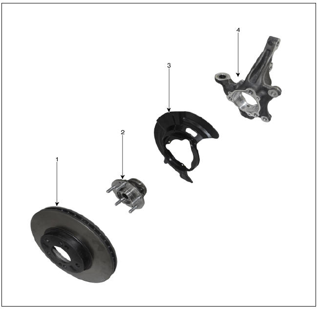
- Brake disc
- Hub assembly
- Dust cover
- Knuckle
Front Hub / Knuckle / Repair Procedures
Removal
- Remove the wheel and tire.
Tightening torque : 107.9 - 127.5 N*m (11.0 - 13.0 kgf*m, 79.6 - 94.0 lb*ft)

Warning
Be careful not to damage the wheel nuts when removing the wheel and tire.
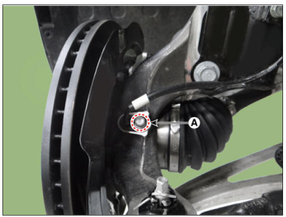
- By hammering on a chisel, unlock the driveshaft lock hub nut caulking.

Warning
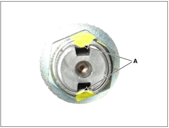
If there is screw thread (A) on the end of the nut, unlock the caulking by using a chisel and then loosen the nut to prevent damaging driveshaft screw thread.

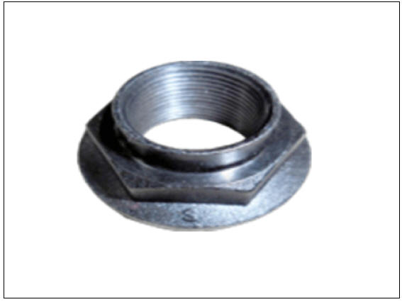
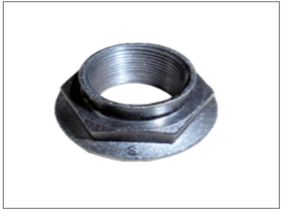
- Remove the caulking nut (A) from the front axle.
Tightening torque : 274.6 - 294.2 N*m (28.0 - 30.0 kgf*m, 202.5 - 217.0 lb*ft)

Warning
The driveshaft lock nut must be replaced with new one. When
replacing the drive lock hub nut, use only the
nut with screw thread (A) on the end
- Tighten the driveshaft lock hub nut to the specified tightening torque, and caulk by using a chisel and hammer.
- If there are two key seats, perform on all two seats.
Caulking depth (A) : 1.5 mm (0.0591 in)

- Remove the front caliper.
(Refer to Brake System - "Front disck brake")
- Remove the wheel speed sensor bolt (A).
Tightening torque : 6.8 - 10.7 N*m (0.7 - 1.1 kgf*m, 5.0 - 7.9 lb*ft)
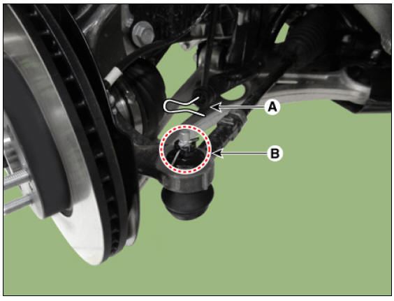
- Remove the tie rod end pin (A) and nub (B).
Tightening torque : 78.4 - 98.0 N*m (8.0 - 10.0 kgf*m, 57.8 - 72.3 lb*ft)
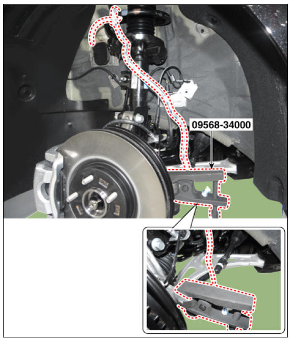
- Remove the knuckle by using the SST (09568-34000).
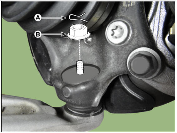
- Loosen the pin (A), and then remove the lower arm nut (B).
Tightening torque : 98.0 - 117.6 N*m (10.0 - 12.0 kgf*m, 72.3 - 86.7 lb*ft)
- Loosen the strut bolt and then remove the front axle.
Tightening torque : 156.9 - 176.5 N*m (16.0 - 18.0 kgf*m, 115.7 - 130.2 Ib*ft)
Disassembly
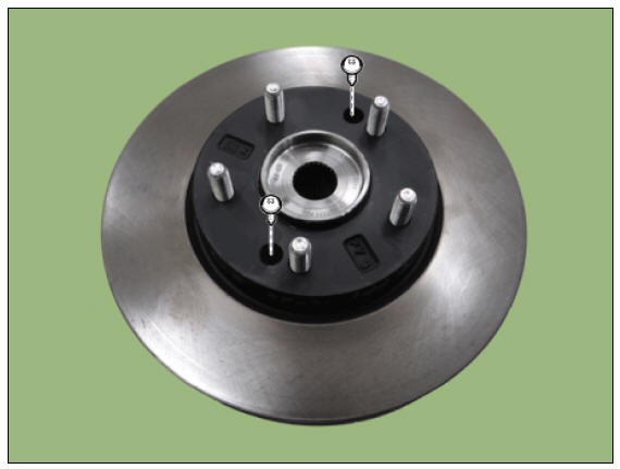
- Loosen the screw, and then remove the brake disc.
Tightening torque : 4.9 - 5.8 N*m (0.5 - 0.6 kgf*m, 3.6 - 4.3 Ib*ft)
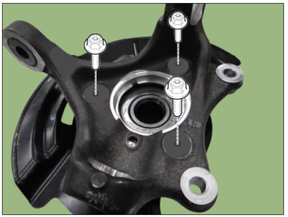
- Remove the hub assembly mounting bolts from the knuckle.
Tightening torque : 88.2 - 107.8 N*m (9.0 - 11.0 kgf*m, 65.0 - 79.5 lb*ft)
- Loosen the dust cover bolts and then remove the dust cover.
Tightening torque : 6.8 - 10.7 N*m (0.7 - 1.1 kgf*m, 5.0 - 7.9 lb*ft)

Inspection
- Check the hub for cracks and the splines for wear.
- Check the brake disc for scoring and damage.
- Check the knuckle for cracks
- Check the bearing for cracks or damage.
Removal and
Installation
- Remove the front wheel and tire.
(Refer to Suspension System - "Wheel")
- Disconnect the front wheel speed sensor (A).
Tightening torque : 7.8 - 11.8 N*m (0.8 - 1.2 kgf*m, 5.8 - 8.7 lb*ft)
- Disconnect the brake hose bracket (A) by loosening the bolt.
Tightening torque : 8.8 - 13.7 N*m (0.9 - 1.4 kgf*m, 6.5 - 10.1 lb*ft)
- By hammering on a chisel, unlock the driveshaft lock hub nut caulking.

Warning
If there is screw thread (A) on the end of the nut, unlock the
caulking by using a chisel and then loosen the nut
to prevent damaging driveshaft screw thread.
- Remove the caulking nut (A) from the front axle.
Tightening torque: 274.6 - 294.2 N*m (28.0 - 30.0 kgf*m, 202.5 - 217.0 lb*ft)
Warning
The driveshaft lock nut must be replaced with new one. When
replacing the drive lock hub nut, use only the
nut with screw thread (A) on the end.

- Tighten the driveshaft lock hub nut to the specified tightening torque, and caulk by using a chisel and hammer.
- If there are two key seats, perform on all two seats.
Caulking depth (A) : 1.5 mm (0.0591 in)
- Remove the front brake disc.
(Refer to Brake System - "Front Disc Brake")
- Using a SST (09517-4E000), disconnect the driveshaft from the axle hub.
Warning
Do not pull or twist excessively to remove the axle when the drive shaft is disassembled.
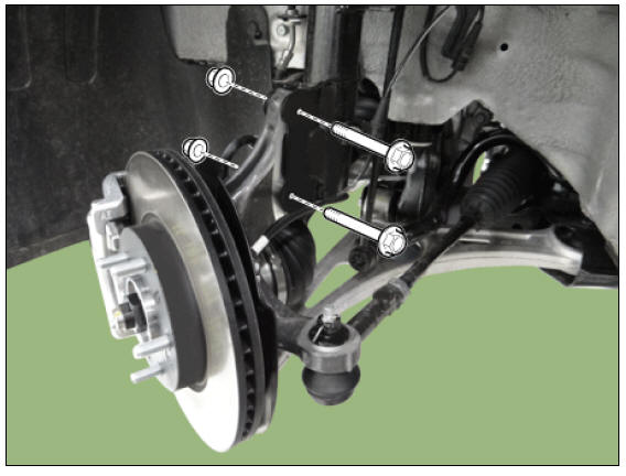
- Loosen the bolts and remove the hub bearing assembly (A) from the front knuckle.
Tightening torque: 88.3 - 107.9 N*m (9.0 - 11.0 kgf*m, 65.1 - 79.6 lb*ft)
- Install in the reverse order of removal.
READ NEXT:
 Rear Axle Assembly / Rear Hub - Carrier
Components
Disc
Dust cover
Rear hub
Rear Knuckle
Rear Hub - Carrier / Repair Procedures
Removal
Remove the tire (A).
Tightening torque :
107.9 - 127.5 N*m (11.0 - 13.0 kgf*m, 79.6 - 94.0 lb*ft)
Warning
Be careful not t
Suspension System
Service
Data
Front Suspension
Rear Suspension
Wheel & Tire
Wheel Alignment
Tightening
Torques
Front Suspension
Rear Suspension
Special Service Tools
Tool Name / Number / IIIustration
/ Description
Troubleshooting - Suspension System
Symptom:
Heavy weight feeling on steering wheel
Expected cause - Countermeasure
Faulty on front wheel alignment - Adjust or
repair
Over rotation resistance of lower arm
ball joint - Replace
Over rotation resistance of strut
b
SEE MORE:
Rear Stabilizer Bar Repair procedures
Removal
Disconnect the battery negative cable.
Remove the wheel and tire.
Tightening torque:
107.9 - 127.5 N*m (11.0 - 13.0 kgf*m, 79.6 - 94.0 lb*ft)
Warning
Be careful not to damage the wheel nuts when removing the wheel and
tire.
Rheostat | Front Fog Lamps Repair procedures
Connector and Terminal Function
Rheostat Repair procedures
Removal
Disconnect the negative (-) battery terminal.
Remove the crash pad lower panel.
(Refer to Body - "Crash Pad Lower Panel")
Remove the crash
Categories
- Home
- KIA Niro EV, Hybrid - Second generation - (SG2) (2021-2024) - Owner's manual
- Kia Niro - First generation - (DE) (2017-2022) - Service and Repair Manual
- Contact Us