KIA Niro: System Operation Specification
Kia Niro - First generation - (DE) (2017-2022) - Service and Repair Manual / Advanced Driver Assistance System (ADAS) / Parking Distance Warning (PDW) / System Operation Specification
Initial mode
- System initializing time
- PDW-F : 500ms after IGN1+ initial D Gear + below 10 Km/h
- PDW-R : 500ms after IGN1+ initial R Gear
- PDW recognizes LID and sets the sensor ID up during initialization.
- PDW activates each sensor and then executes the diagnosis after finishing initialization of IPM(BCM).
- PDW starting buzzer is normally worked, when sensor does not send an error message and after finishing error diagnosis.
- If any failure is received from the any sensors, PDW starting buzzer does not work but the failure alarm is operated for a moment.
If you have display option, warning sign is also shown on it.
Warning
Buzzer for sensor failure is operated once, but display is shown continuously until it is repaired completely.
- BCM memorizes the completed initializing status of sensor.
Normal mode
- PDW-F : Lin communication starts and keeps the routine after IGN1 ON+D
gear + below 10 km/h.
PDW-R : Lin communication starts and keeps the routine after IGN1 ON+R gear
- After initializing, the routine starts at once without PDW starting warning sound.
- Alarms of obstacle consists of 3 level 1,2,3 step and 1,2 alarm sounds intermittently and 3 alarm sounds continuously. 1 level alarm doesn't exist in the front ultrasonic sensor.
- In display, the data of each sensor is sent from BCM to display, for example cluster. CAN communication is used for transmission and maximum gateway time is 50ms.
- The efficient vehicle speed of PDW operation is under 10Km/h.
- Operation doesn't start or stops at gear N, P.
Sensing Area
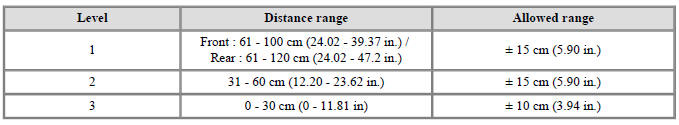
*Measurement condition : PVC pipe - Diameter 75 mm (0.0394 in.), length 1 m (39.37 in.), at normal temperature Display Alarm
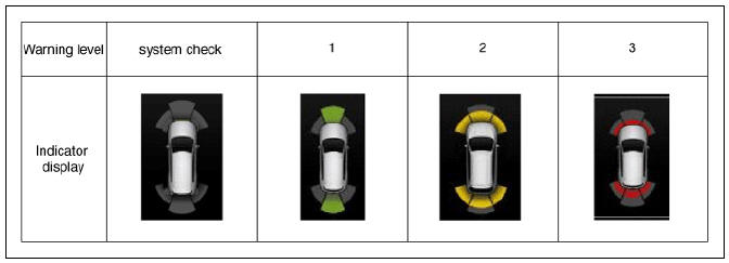
Display Alarm Indicator Specification
READ NEXT:
 Parking Distance Warning (PDW) Sensor
Connector and Terminal function
Circuit Diagram
Removal
PDW-F (Parking Distance Warning-Forward) Sensor
Remove the front bumper assembly.
(Refer to Body - "Front Bumper Assembly")
Disconnect the connector (A) from t
SEE MORE:
Sun visor
Operation
Pull down and unsnap it from the
bracket (1).
Swing it to the side (2).
Pull down and slide the mirror
cover (3) to use the vanity mirror.
The ticket holder (4) is provided for
the purpose of holding a tollgate
ticke
Fuel Pressure Sensor (FPS)
Description
Installed on top of the low pressure fuel pump, the Fuel Pressure Sensor
(FPS) measures the pressure
in the low pressure fuel line.
Based on the fuel pressure measured by the FPS and the amount of fuel consumed,
the fuel pump
co
Categories
- Home
- KIA Niro EV, Hybrid - Second generation - (SG2) (2021-2024) - Owner's manual
- Kia Niro - First generation - (DE) (2017-2022) - Service and Repair Manual
- Contact Us