KIA Niro: Steering Angle Sensor (SAS) Calibration | Part replacement (Power steering ECU)
Warning
- Check that the battery is fully charged before "Steering Angle Sensor (SAS) Calibration".
- Be careful not to disconnect any cables connected to the vehicle or scan tool during "Steering Angle Sensor (SAS) Calibration".
- After completing the "Steering Angle Sensor (SAS) Calibration", switch off the ignition and wait for several seconds. Then, start the engine to confirm normal operation of the vehicle.
- Connect self-diagnosis connector (16pins) located under the driver side crash pad to self-diagnosis device, and then turn the selfdiagnosis device after key is ON.
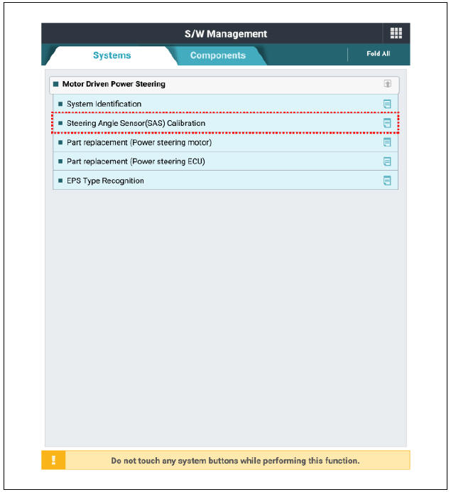
- Select the "vehicle model" and "Motor Driven Power Steering" on KDS vehicle selection screen.
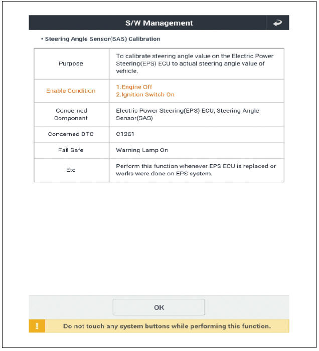
- Select the "Steering Angle Sensor (SAS) Calibration" on KDS screen, then select OK.
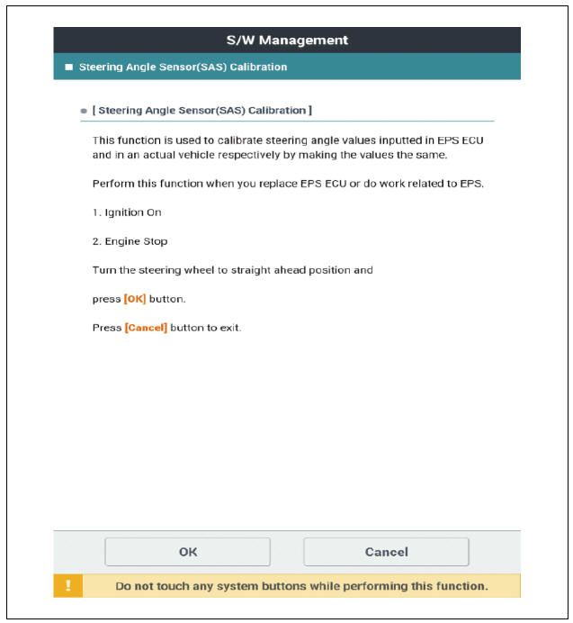
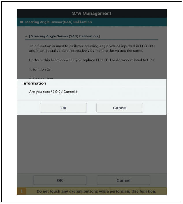
- Proceed with the test according to the screen instructions.
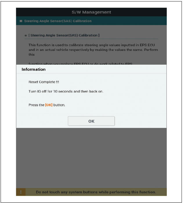
- Remove the DTC.
- Turn off the IG switch and wait for 10 seconds or more before starting the engine. And then make sure that MDPS works properly.
Part replacement (Power steering ECU)
Replacement
Warning
- If a DTC occurs in the ECU, check the connectors and wiring. If no problem is found, replace the ECU.
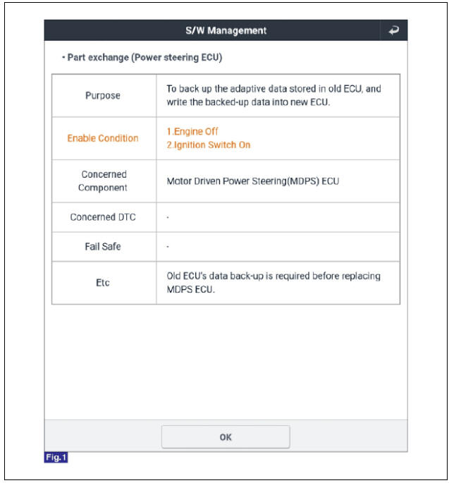
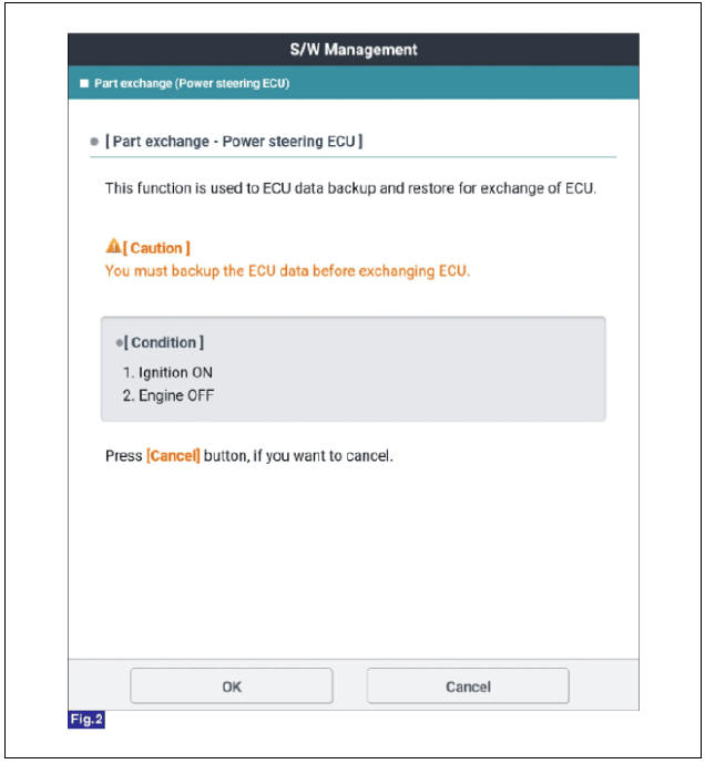
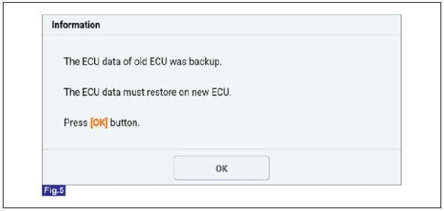
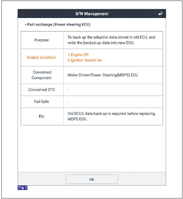
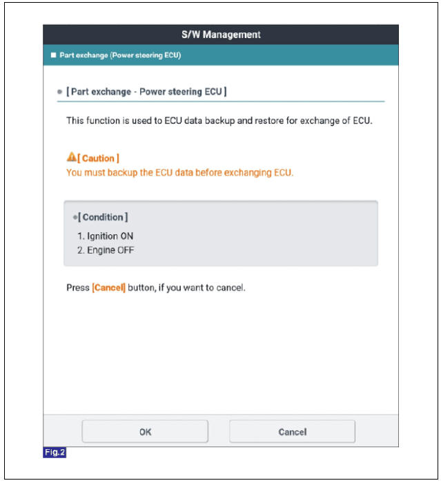
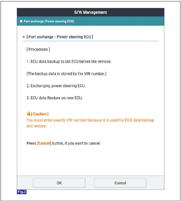
- Before replacing the MDPS ECU, use the diagnostic device to read the settings of the old ECU
- Perform the "Motor Driven Power Steering" by KDS following in the order below.
(1) Connect self-diagnosis connector (16pins) located under the driver side crash pad to self-diagnosis device, and then turn the self-diagnosis device after key is ON.
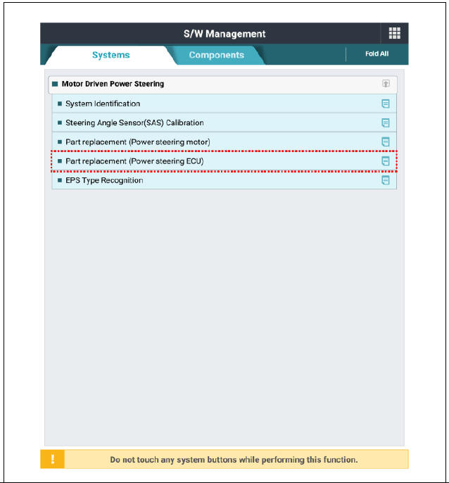
(2) Select the "vehicle model" and "Motor Driven Power Steering" on KDS vehicle selection screen.
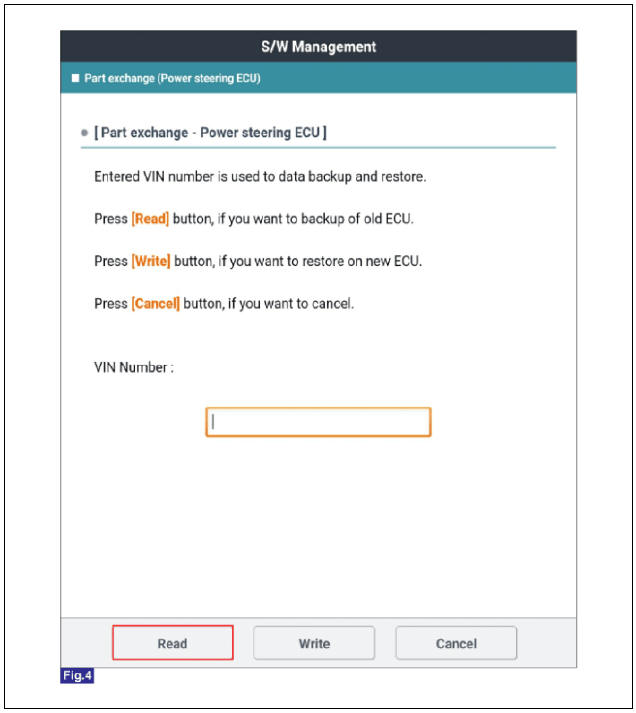
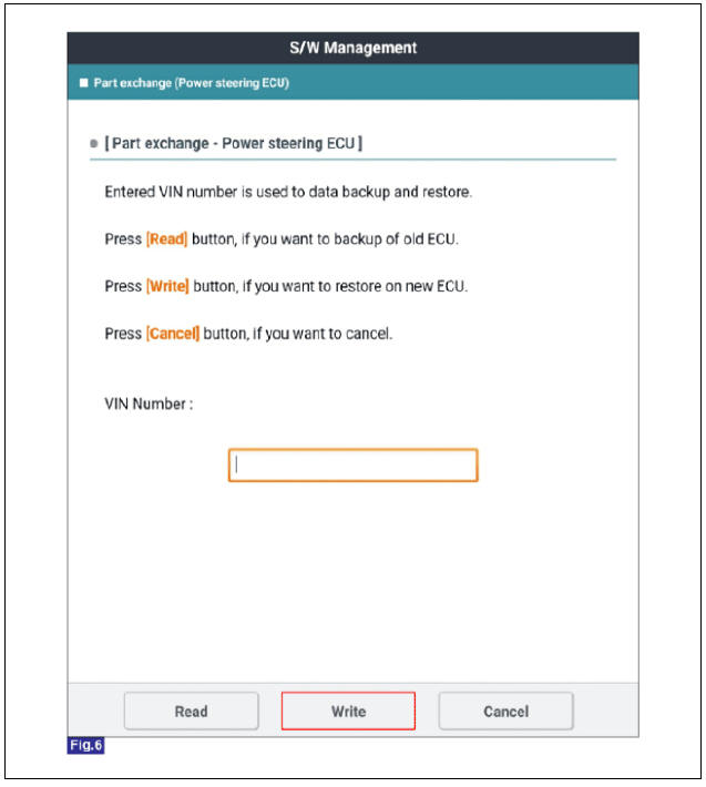
(3) Select the "Part replacement (Power steering ECU)" on KDS screen, then select OK.
(4) Proceed with the test according to the screen instructions.

Warning
If a DTC occurs in the ECU, check the connectors and wiring. If no problem is found, replace the ECU.
- Disconnect the battery negative terminal.
- Remove the crash pad lower panel.
(Refer to Body - "Crash pad lower panel")
- Remove the knee airbag (KAB) module.
(Refer to Restraint - "Knee Airbag (KAB) Module")
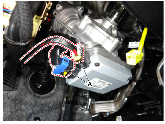
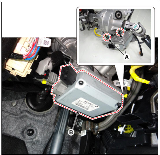
- Disconnect the MDPS ECU connectors (A).
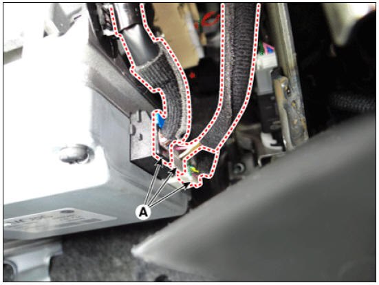
- Loosen the mounting bolts (A) and then remove the MDPS ECU (B).
Tightening torque : 19.6 - 23.5 N*m (2.0 - 2.4 kgf*m, 14.5 - 17.4 lb*ft)
- Install in the reverse order of removal.
- Perform the "Motor Driven Power Steering" by KDS following in the order below.
(1) Connect self-diagnosis connector (16pins) located under the driver side crash pad to self-diagnosis device, and then turn the self-diagnosis device after key is ON.
(2) Select the "vehicle model" and "Motor Driven Power Steering" on KDS vehicle selection screen.
(3) Select the "Part replacement (Power steering ECU)" on KDS screen, then select OK.

(4) Proceed with the test according to the screen instructions.
- Perform the "Steering Angle Sensor (SAS) Calibration" and "Set the steering feel torque to zero".
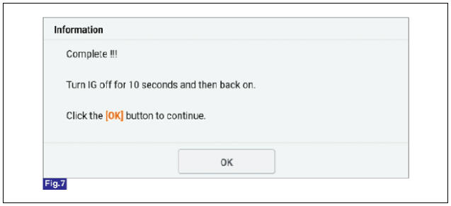
- Turn off the IGN switch and wait for 10 seconds or more. Then check the operation after starting the engine.
READ NEXT:
 Steering Angle Sensor (SAS) Calibration and Set the steering feel torque to
zero
Steering Angle Sensor (SAS) Calibration and Set the steering feel torque to
zero
Diagnosis with KDS
Warning
Check that the battery is fully charged before "Steering Angle
Sensor (SAS) Calibration".
Be careful not to disconnect any cables connected to the
vehicle or scan tool during "Steering Angle Sens
MDPS Tuning Data Setting | Steering Column and Shaft Repair procedures
Since MDPS can store various tuning maps with different steering feelings in the ECU and different steering feelings depending on the application area and the vehicle engine type, it is necessary to set codes appropriate for the applicatio
SEE MORE:
Engine Oil Level
Warning
Be sure that the vehicle is on level ground.
Warm up and stop the engine, and then wait for 5 minutes.
Turn the engine off and wait for a few minutes (about 5 minutes) for the
oil to return to the oil pan.
Pull the dipstick out, w
Identification Number Locations
Identification Numbers
Identification Number Description
Vehicle Identification Number
World Manufacturer Identifier (WMI)
KNA : Passenger vehicle, MPV(Multipurpose Passenger Vehicle)/SUV(Sports
Utility Vehicle)/RV(Recreational
Categories
- Home
- KIA Niro EV, Hybrid - Second generation - (SG2) (2021-2024) - Owner's manual
- Kia Niro - First generation - (DE) (2017-2022) - Service and Repair Manual
- Contact Us