KIA Niro: SRS Control Module (SRSCM) Repair procedures
SRS Control Module (SRSCM) Description and operation
The primary purpose of the SRSCM (Supplemental Restraints System Control Module) is to determine between an event that warrants restraint system deployment and an event that does not. The SRSCM must decide whether to deploy the restraint system or not. After determining that pretensioners and/or airbag deployment is required, the SRSCM must supply sufficient power to the pretensioners and airbag igniters to initiate deployment.
The SRSCM determines that an impact may require deployment of the pretensioners and airbags from data obtained from impact sensors and other components in conjunction with a safing function.
The SRSCM will not be ready to detect a crash or to activate the restraint system devices until the signals in the SRSCM circuitry stabilize.
It is possible that the SRSCM could activate the safety restraint devices in approximately 2 seconds but is guaranteed to fully function after prove-out is completed.
The SRSCM must perform a diagnostic routine and light a system readiness indicator at key-on. The system must perform a continuous diagnostic routine and provide fault annunciation through a warning lamp indicator in the event of fault detection. A serial diagnostic communication interface will be used to facilitate servicing of the restraint control system.
SRS Control Module (SRSCM) Components and components location
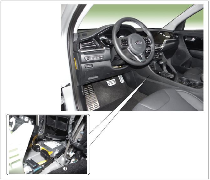
- Supplemental Restraint System Control Module (SRSCM)
SRS Control Module (SRSCM) Repair procedures
Removal
- Remove the battery (-) cable.
Warning
Disconnect the battery negative terminal and wait for at least thirty seconds before beginning work.
- Remove the driver's seat.
(Refer to Body - "Front Seat Assembly")
- Remove the front door scuff trim.
(Refer to Body - "Door Scuff Ttrim")
- Remove the cowl side trim.
(Refer to Body - "Cowl Side Trim")
- It is removing the floor console assembly.
(Refer to Body - "Floor Console Assembly")
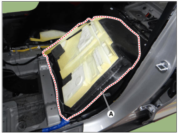
- Fold the floor carpet (A) to backward.
- Remove the clip and take off the rear heating ducts (A).
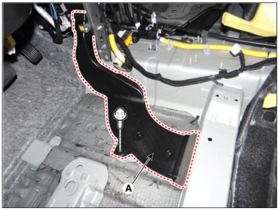
- Remove the cowl cross bar and the bracket (A).
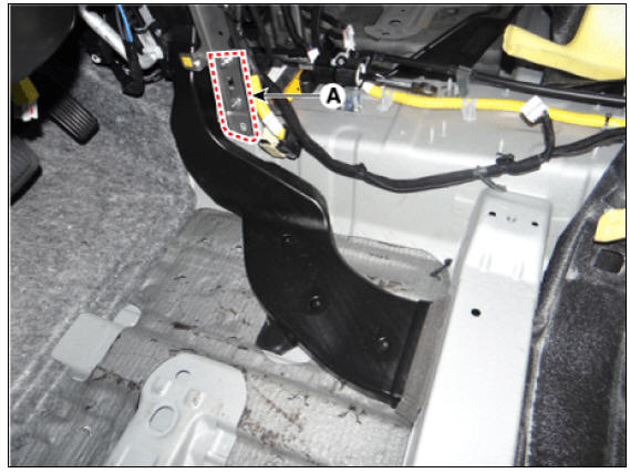
- Pull the locking lever of the airbag system control module (SRSCM) connector and remove the connector (A)
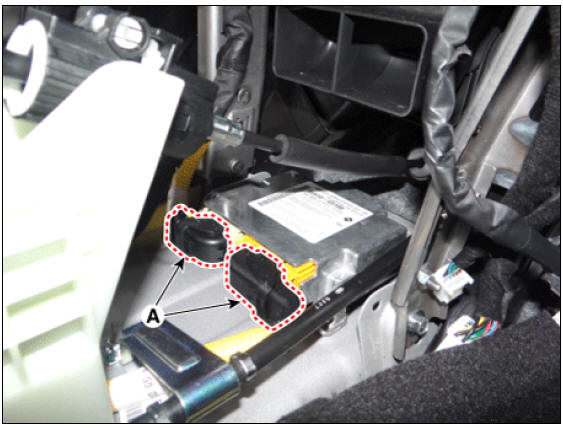
- Unscrew the nuts and remove the airbag system control module (A).
Tightening torque: 8.0 - 10.0N.m(0.8 - 1.0 kgf.m, 5.9 - 7.3 lb-ft)

Warning
You must remove or install SRSCM or other SRS components with the ignition switch OFF to avoid accidental airbag deployment.
Installation
- Install in the reverse order of removal.
Variant coding
After replacing the SRSCM with a new one, the "Variant Coding" procedure MUST be performed.
Warning
1) In SRSCM variant coding mode, the airbag warning lamp periodically flickers (ON: 0.5sec., OFF: 0.5sec.) until the coding is normally completed.
2) If the variant coding has failed, DTC (ACU Coding Error) will be displayed and the warning lamp will be turned on.
In this case, perform the variant coding procedure again after confirming the cause in "DTC Fault State Information".
Variant Coding can be performed up to 255 times, but if the number of coding work exceeds 255 times, DTC (Exceed Maximum coding Number) will be displayed and SRSCM must be replaced.
3) If the battery voltage is low (less than 9V), DTC will be displayed. In this case, charge the battery before anything else, and then perform the variant coding procedure.
DTC (ACU Coding Error) and (Battery Voltage Low) may be displayed simultaneously.
Variant coding Procedure
On-Line on KDS
- Switch "OFF" ignition, and connect KDS.
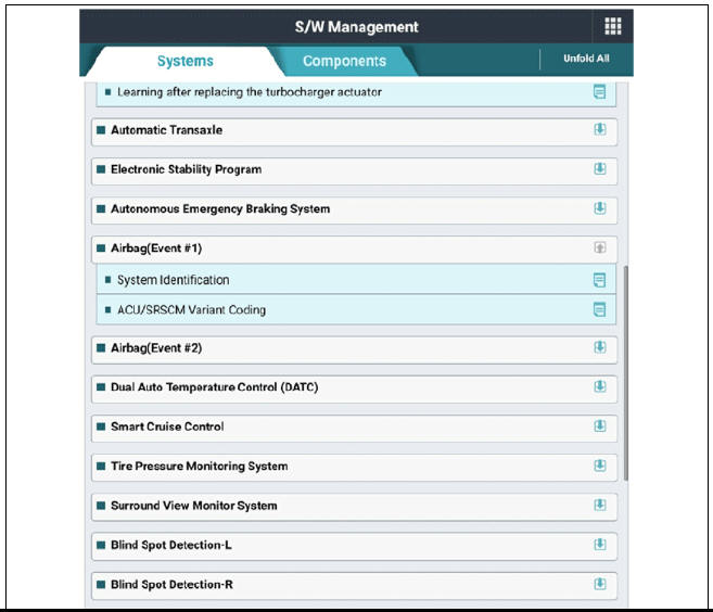
- With ignition "ON" & Engine "OFF", select vehicle name and airbag system.
- Select Variant coding mode
- Enter the VIN code.
Off-Line on KDS
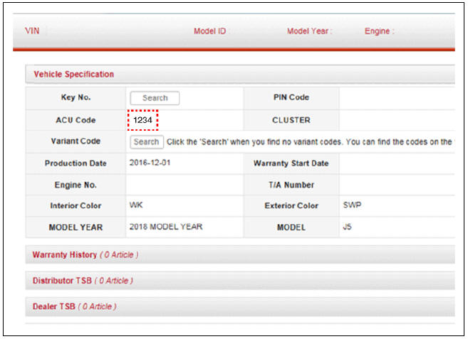
- Confirm the ACU variant coding code from the GSW server after inputting the VIN to the GSW sever.
- Switch "OFF" ignition, and connect KDS.
- With ignition "ON" & Engine "OFF", select vehicle name and airbag system.
- Select Variant coding mode.
- Input the ACU coding code.

READ NEXT:
 Front Impact Sensor (FIS) | Side Impact Sensor (SIS)
Front Impact Sensor (FIS) Description and operation
Description
The front impact sensor (FIS) is installed in the Front End Module (FEM). They are remote sensors that detect acceleration due to a collision at its mounting location. The p
Seat Belt Buckle Switch (BS)
Seat Belt Buckle Switch (BS) Description and operation
Description
The SRSCM shall monitor the status of the driver and front passenger seat
belt buckle. The SRSCM
provides one pin each for the driver and front passenger seat belt buckle status
SEE MORE:
Driveshaft and axle
Service Data
Tightening Torques
Lubricants
Special Service Tools
Tool Name / Number/ Illustration/ Description
Ball joint puller
09568-34000/ / Remove the ball
joint
Puller
09495-33000/ /Used for removal of
spider assembly
Engine compartment (Kia Niro Hybrid only)
Smartstream G1.6 GDi HEV
Smartstream G1.6 GDi PHEV
Engine coolant reservoir
Brake fluid reservoir
Air cleaner
Engine oil filler cap
Engine oil dipstick
Windshield washer fluid reservoir
Fuse box
Inverter coolant reservoir
Categories
- Home
- KIA Niro EV, Hybrid - Second generation - (SG2) (2021-2024) - Owner's manual
- Kia Niro - First generation - (DE) (2017-2022) - Service and Repair Manual
- Contact Us