KIA Niro: Front Impact Sensor (FIS) | Side Impact Sensor (SIS)
Front Impact Sensor (FIS) Description and operation
Description
- The front impact sensor (FIS) is installed in the Front End Module (FEM). They are remote sensors that detect acceleration due to a collision at its mounting location. The primary purpose of the Front Impact Sensor (FIS) is to provide an indication of a collision. The Front Impact Sensor (FIS) sends acceleration data to the SRSCM.
- They are remote sensors that detect acceleration due to a collision at its mounting location.
- The primary purpose of the Front Impact Sensor (FIS) is to provide an indication of a collision. The Front Impact Sensor (FIS) sends acceleration data to the SRSCM.
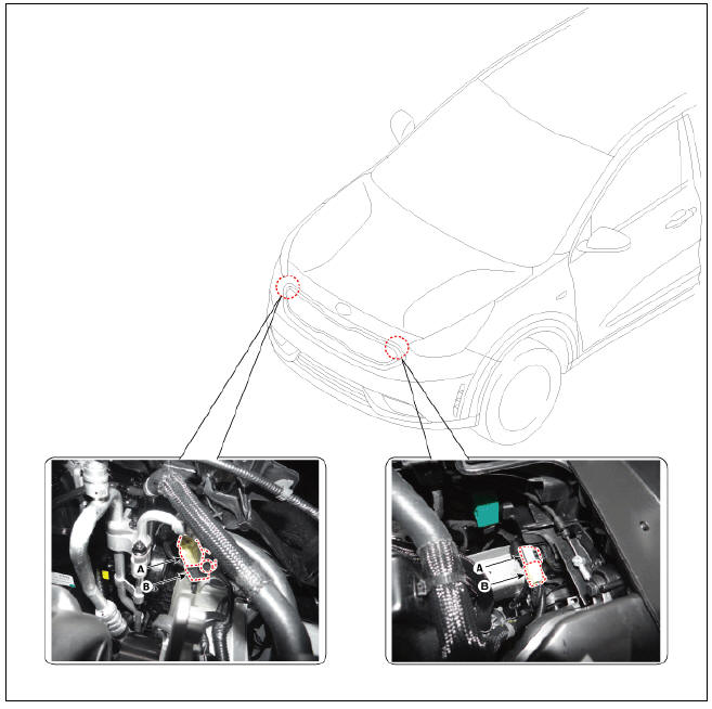
Front Impact Sensor (FIS) Components and components location

Front Impact Sensor (FIS) Repair procedures
Removal
- Disconnect the battery negative terminal, and wait for at least thirty seconds before beginning work.
- Disconnect the front impact sensor connector (A).
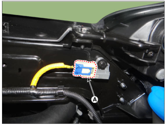
- Remove the front impact sensor (A) by loosening the nut after disconnecting the connector (B).
Tightening torque: 8.0 - 10.0 N.m (0.8 - 1.0 kgf.m, 5.9 - 7.3 lb-ft)
Installation
- Install in the reverse order of removal
Warning
Do not turn the ignition switch ON and do not connect the battery terminal while replacing the front impact sensor.
Side Impact Sensor (SIS)
Description
- Side Impact Sensor (SIS) system consists of two Pressure Side Impact Sensor (P-SIS) which are installed at each center of the front door module (LH and RH) and two SIS which are installed at each center pillar nearby (LH and RH) and two rear SIS which are installed in the rear pillar (LH and RH).
- Pressure Side Impact Sensor is also called P-SIS because it detects pressure due to collision at its mounting location.
- Side Impact Sensor is also called A-SIS because it detects acceleration.
- SRSCM decides deployment of the airbag and the time of deployment through the collision signal of the SIS when the collision occurred
Side Impact Sensor (SIS) Components and components location

Side Impact Sensor (SIS) Repair procedures
Removal
Pressure side impact sensor (P-SIS)
- Disconnect the battery negative terminal, and wait for at least thirty seconds before beginning work.
- Remove the front door trim.
(Refer to Body (Interior and Exterior) - "Front Door Trim")
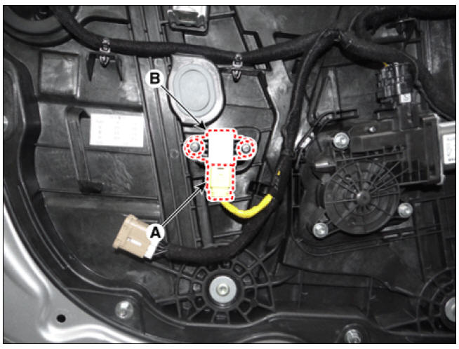
- Remove the pressure side impact sensor (A) by loosening the screws and then disconnect the connector (B).
Tightening torque: 2.0 - 3.0 N.m (0.2 - 0.3 kgf.m, 1.5 - 2.2 lb-ft)
Front Gravity side impact sensor (G-SIS)
- Disconnect the battery negative terminal, and wait for at least thirty seconds before beginning work.
- It separates the center pillar trim.
(Refer to Body - "Built-in Trim")
- Remove the side impact sensor connector (A).
- Loosen the mounting bolts and remove the side impact sensor (B).
Tightening torque: 8.0 - 10.0 N.m (0.8 - 1.0 kgf.m, 5.9 - 7.3 lb-ft) Installation

Installation
Pressure side impact sensor (P-SIS)
- Install in the reverse order of removal.
- After replacing the side impact sensors must ensure that the system is operating normally.
Warning
Turn the ignition switch ON; the SRS indicator light should be turned on for about six seconds and then go off
Warning
- You must comply with the specified tightening torques with the tool specified because Pressure - Side Impact Sensors (P-SIS) may be broken or the POP-NUT may be rotated.
- Problems may be occurred in the durability of P-SIS or impact sensing performance may be depreciated if POP-NUT is rotated.
- The door module must not be transformed because SRSCM judges a impact through the pressure sensor in the door module.
Front Gravity side impact sensor (G-SIS)
- Install in the reverse order of removal.
Warning
- You must comply with the specified tightening torques with the tool specified because Pressure - Side Impact Sensors (P-SIS) may be broken or the POP-NUT may be rotated.
- Problems may be occurred in the durability of P-SIS or impact sensing performance may be depreciated if POP-NUT is rotated.
- The door module must not be transformed because SRSCM judges a impact through the pressure sensor in the door module.
READ NEXT:
 Seat Belt Buckle Switch (BS)
Seat Belt Buckle Switch (BS) Description and operation
Description
The SRSCM shall monitor the status of the driver and front passenger seat
belt buckle. The SRSCM
provides one pin each for the driver and front passenger seat belt buckle status
SEE MORE:
Necessary vehicle inspections
Be sure to check the following fluid levels
on a regular basis at the exact interval:
Engine oil
Engine coolant
Brake fluid
Washer fluid
For more details, refer to "Maintenance"
WARNING
Focus on the road while driving. The
Crash Pad Main Lower Panel
Crash pad main lower panel
Replacement
Warning
Put on gloves to protect your hands.
Warning
Use a plastic panel removal tool to remove interior trim pieces
without marring the surface.
Be careful not to bend or scratch the trim
Categories
- Home
- KIA Niro EV, Hybrid - Second generation - (SG2) (2021-2024) - Owner's manual
- Kia Niro - First generation - (DE) (2017-2022) - Service and Repair Manual
- Contact Us