KIA Niro: Service Point Target Auto Calibration (SPTAC) Procedure
Kia Niro - First generation - (DE) (2017-2022) - Service and Repair Manual / Advanced Driver Assistance System (ADAS) / Service Point Target Auto Calibration (SPTAC) Procedure
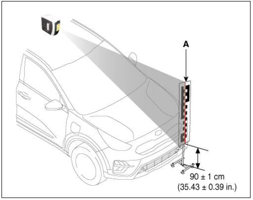
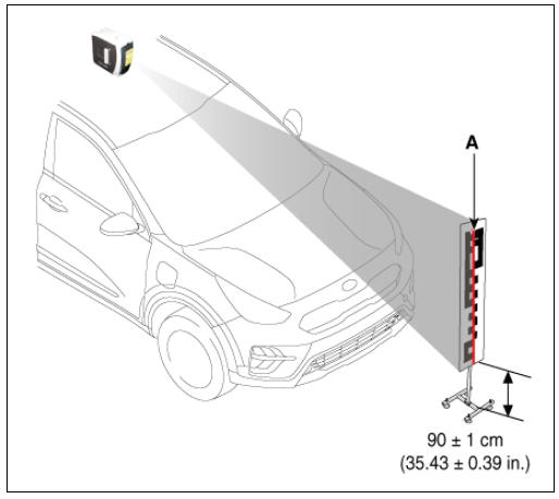
- Install the SST (09964-C1200) on the roof center above the vehicle's front windshield.
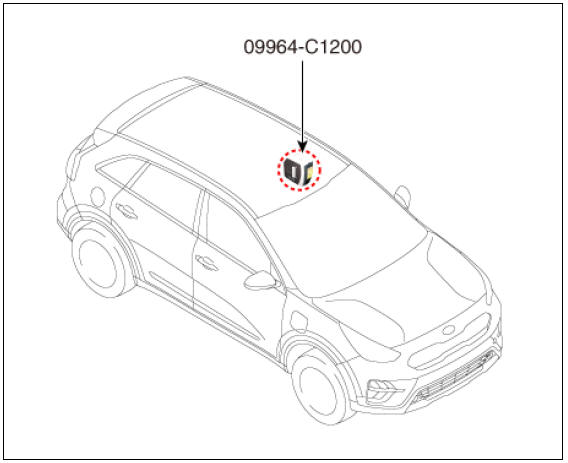
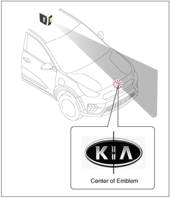
- Have the laser illuminate starting from the roof center and to passing through the emblem center.
Warning
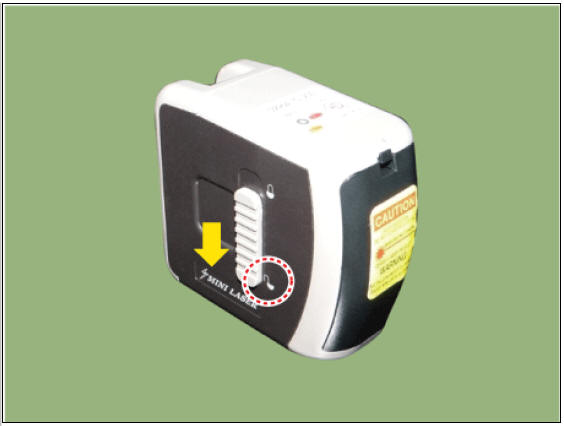
The level laser must be set to 'ON' and the holding (locking)
function is not used.
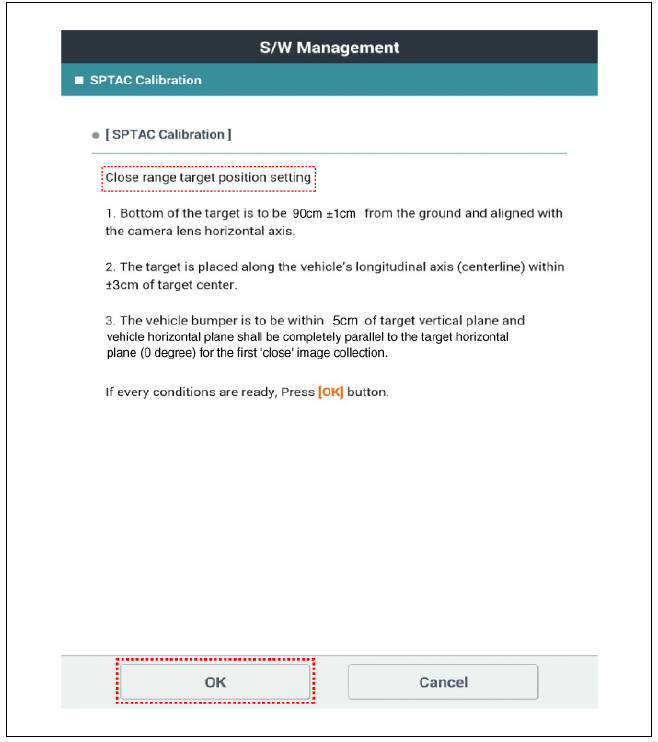
- Place the calibration target (09890-3V100) so that it adheres by 0 cm to the bumper front. (max. tolerance: 5 cm)
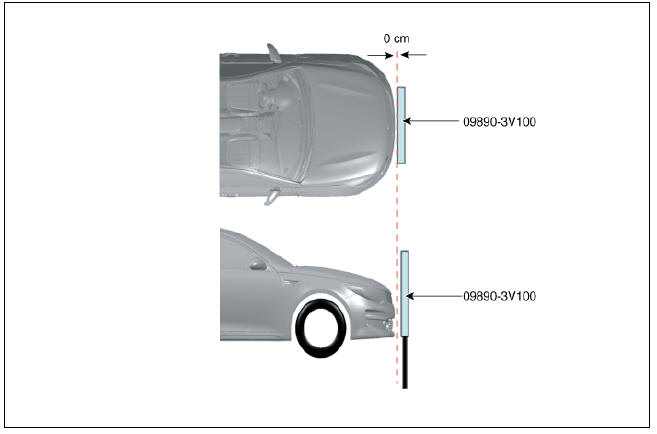
- Set the calibration target height to 90 +- 1 cm (35.43 +- 0.39 in.) from the ground and align the center of calibration target with center line (A) of laser beam.
Warning
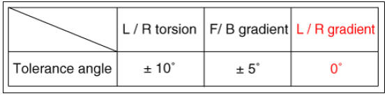
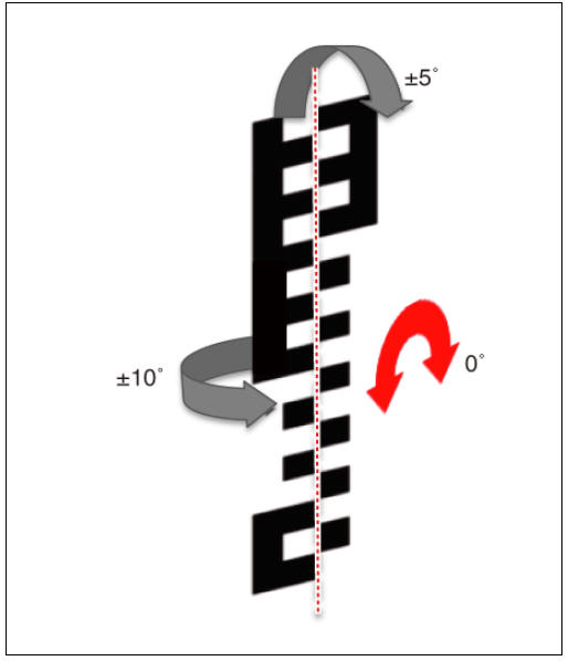
The vehicle horizontal plane shall be completely parallel to the target horizontal plane (0 degree).
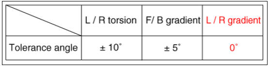
- Align the calibration target (09890-3V100) referring to the
below tolerance angle.

- Mounting area must not have cross hatch patterns or textual markings near the target.
- Target should be well lit for optimal performance using non-fluctuating illumination. There shall be no continuous shadows cast on the target.
- The light should be directed toward the target front and the target front should be brighter than the target rear and target.
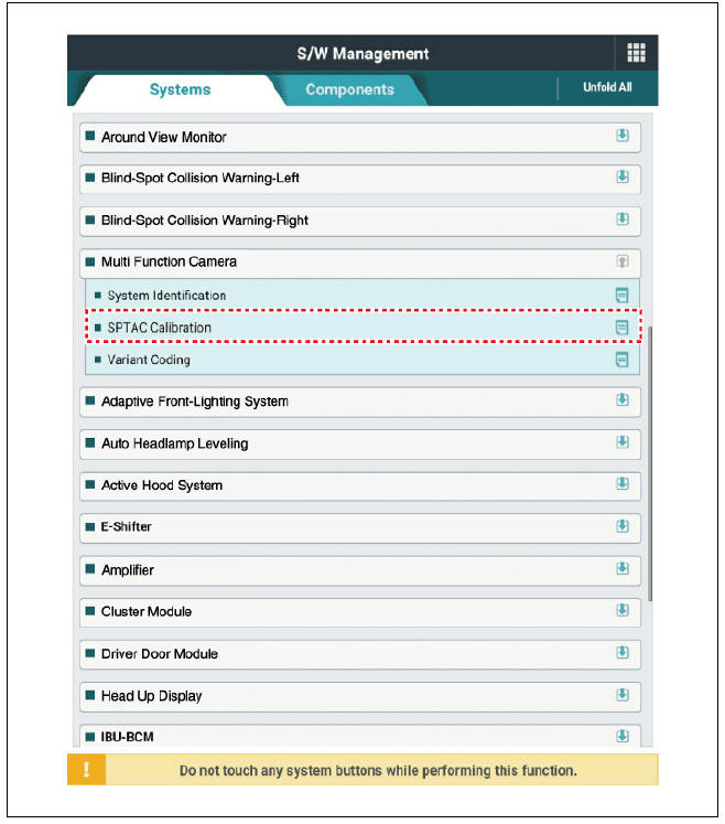
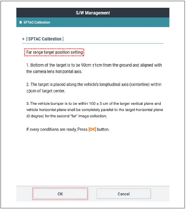
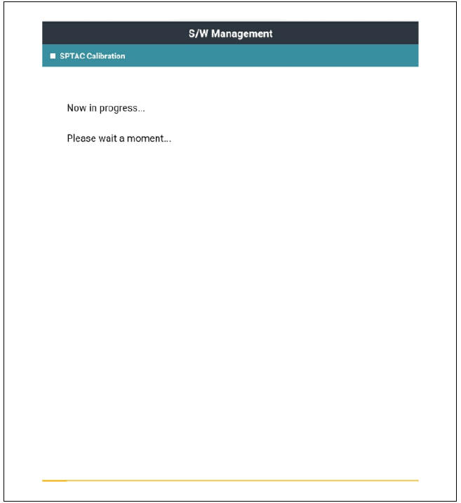
- Perform the "SPTAC Calibration" using the KDS.
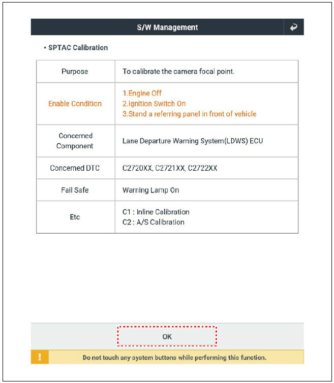
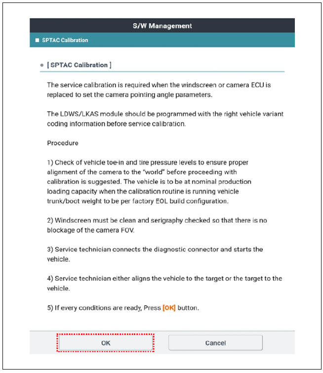
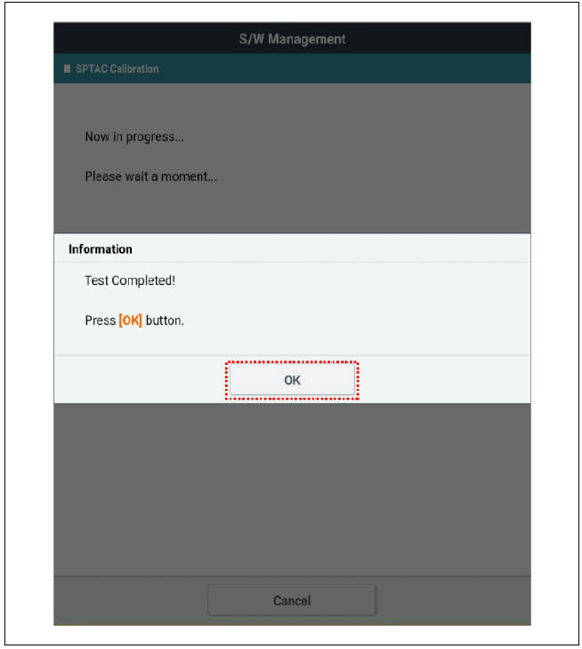
- Perform the short-distance calibration by selecting the "OK" message on the KDS after checking the calibration target location.
- Move the calibration target (09890-3V100) at 100 cm (39.37 in.) from the bumper. (max. tolerance : 5 cm (1.97 in.))
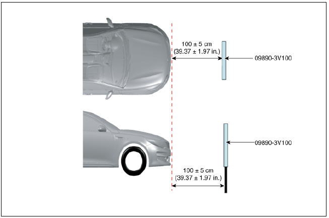
- Align the center of calibration target with center line (A) of laser beam.
Warning
The vehicle horizontal plane shall be completely parallel to the target horizontal plane (0 degree).
- Align the calibration target (09890-3V100) referring to the
below tolerance angle.
- Mounting area must not have cross hatch patterns or textual markings near the target.
- Target should be well lit for optimal performance using non-fluctuating illumination. There shall be no continuous shadows cast on the target.
- The light should be directed toward the target front and the target front should be brighter than the target rear and target.
- Perform the long-distance calibration by selecting the "OK" message on the KDS after checking the calibration target location.
- Clear the diagnostic trouble codes (DTC) using the KDS.
- Check the DTC and warning lamp.
READ NEXT:
 Smart Cruise Control (SCC)
Smart Cruise Control (SCC) switch
Front radar unit
Description
System Function
Forward Collision-avoidance Assist (FCA) : Detects the risk factors on
the road and warn the driver and activate the
emergency brake to prevent colli
Front Radar Unit
Specification
Circuit Diagram
Front Radar Unit Repair Procedures
Inspection
Warning
Put the vehicle on the level ground.
Take out heavy luggage from the vehicles' seats or tailgate.
Set all tires according to the specified pressur
SEE MORE:
How to connect
Outdoor (if equipped)
Open the cover of the V2L connector.
Close the cover after connecting
home appliances and electronic products
to the power outlet.
Connect the V2L connector to the
charging hole on the vehicle.
Pr
High Voltage Shut-off Procedures
Warning
Be sure to read and follow the "General Safety Information and
Caution" before doing any work related with the high voltage
system. Failure to follow the safety instructions may result in serious
electrical injuries.
Be sure to
Categories
- Home
- KIA Niro EV, Hybrid - Second generation - (SG2) (2021-2024) - Owner's manual
- Kia Niro - First generation - (DE) (2017-2022) - Service and Repair Manual
- Contact Us