KIA Niro: Roadside Assistance
Towing
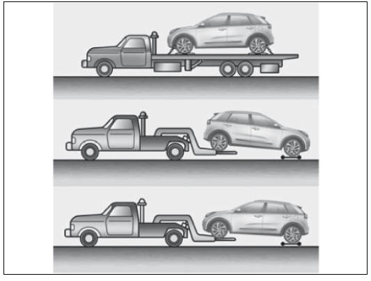
In the event of an accident, the high voltage system must be disabled. The safety plug must be removed from the high voltage battery according to one of the methods described in sections of page 17-20 to disable the vehicle.Towing Niro Vehicle is not different from towing a conventional FWD vehicle.
If emergency towing is necessary, we recommend having it done by an authorized Kia dealer or a commercial tow-truck service. Proper lifting and towing procedures are necessary to prevent damage to the vehicle.The use of wheel dollies or flatbed is recommended.

Warning
- Do not tow with sling-type equipment. Use wheel lift or flatbed equipment.
- Never tow the vehicle with the front wheels on the ground
(forward or backward), as this may
cause fire or damage to the motor.

Emergency Starting
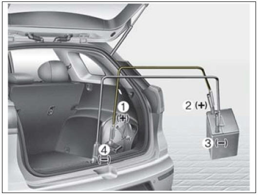
Do not attempt to jump start the high voltage battery, it cannot be jump started. In case of full discharge of the high voltage battery, the vehicle must be towed as mentioned on the previous page. In case the 12V auxiliary battery is discharged, attach jumper cables or starting device to the battery in the luggage side as you would any 12V battery (see image).
Refer to "Emergency Starting" of Owner's Manual for additional information. Connect jumper cables in numerical order and disconnect in reverse order.

Warning
Electrocution Risk
Do not attempt to jump start the Niro high voltage battery.
READ NEXT:
 Front View Camera Unit
Front view camera unit
LKA ON/OFF switch
Description
System Function
Lane Keeping Assist (LKA) : The function detects unintentional lane
departure and assists to keep the lane by using alarms
and MDPS steering control.
High Be
 Front View Camera Unit - Removal
Inspection
In the body electrical system, failure can be quickly diagnosed by using
the vehicle diagnostic system (KDS).
The diagnostic system (KDS) provides the following information.
(1) Self diagnosis : Checking failure and code number
SEE MORE:
 Highway Driving Assist malfunction and limitations
Highway Driving Assist malfunction
A: Check HDA (Motorway Driving
Assist) system
Kia Niro EV
A: Check lane change assist function
When Highway Driving Assist is not
working properly, the warning message
will appear, and the ( ) warning
 Front Seat Belt Retractor | Height Adjuster
Front Seat Belt / Components And Components Location
Front seat belt retractor
Height adjuster
Rear seat belt retractor (side)
Rear seat belt retractor (center)
Front Seat Belt Retractor
Front seat belt retractor
Categories
- Home
- KIA Niro EV, Hybrid - Second generation - (SG2) (2021-2024) - Owner's manual
- Kia Niro - First generation - (DE) (2017-2022) - Service and Repair Manual
- Contact Us
